
A processing method for a spool used in an oil cooler

A processing method and oil cooler technology, applied to valve devices, cocks including cutting devices, engine components, etc., can solve the problems of low processing accuracy and difficult operation, and achieve the effect of improving turning processing accuracy and processing accuracy

Active Publication Date: 2016-03-09
HARBIN TURBINE +1
View PDF6 Cites 0 Cited by
  • Summary
  • Abstract
  • Description
  • Claims
  • Application Information

AI Technical Summary

Problems solved by technology

[0006] In order to solve the problem of low processing accuracy due to the difficulty and complexity of the existing processing method for the spool used in the oil cooler, the present invention provides a processing method for the spool used in the oil cooler

Method used


Image

  • A processing method for a spool used in an oil cooler
  • A processing method for a spool used in an oil cooler
  • A processing method for a spool used in an oil cooler

Examples


specific Embodiment approach 1

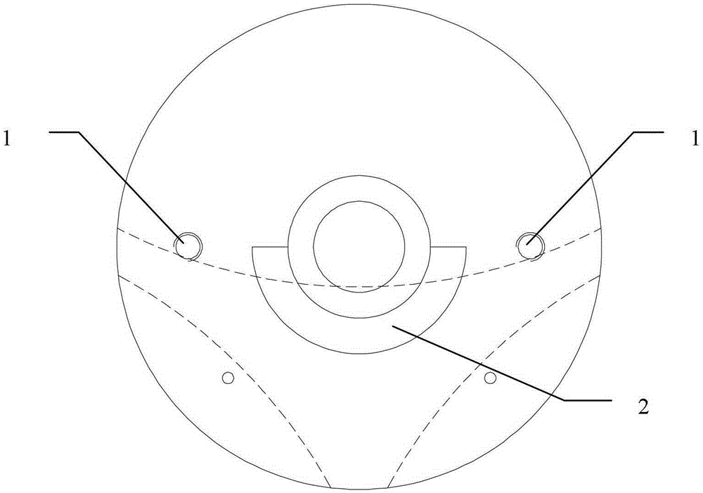
[0020] Specific implementation mode 1. Combination figure 1 Describe this specific embodiment, a kind of processing method of valve core for oil cooler, it is realized by the following steps:

[0021] Step 1. Roughly process the original material to obtain the rough-processed valve core for the oil cooler. The rough-processed valve core for the oil cooler includes the No. 1 cylinder (14), the No. 2 cylinder (15), the semicircular arc surface ( 2) and the cone (16), the lower surface of the No. 1 cylinder (14) and the upper surface of the No. 2 cylinder (15) are fixed, and the No. 1 cylinder (14) and the No. 2 cylinder (15) are coaxial and semicircular The inner side of face (2) is fixed with the end of the side of No. 2 cylinder (15), the upper surface of cone (16) is fixed with the lower surface of No. 2 cylinder (15), and cone (16) is connected with No. 2 cylinder ( 15) Coaxial;

[0022] Step 2, use a boring machine to drill a center hole in the center of the upper surface...

specific Embodiment approach 2

[0030] Embodiment 2. The difference between this embodiment and the method for processing a spool for an oil cooler described in Embodiment 1 is that the diameters of the center holes of the upper and lower outer circles in step 1 are 4mm-6mm.

specific Embodiment approach 3

[0031] Embodiment 3. The difference between this embodiment and the method for processing a spool for an oil cooler described in Embodiment 1 is that in step 3, the turning parameters when turning each outer circle and end face with a lathe are: The speed is 70r / min-90r / min, the feed rate is 0.2mm / r-0.4mm / r, and the cutting depth is 1.2mm-1.8mm.


PUM

PropertyMeasurementUnit
diameteraaaaaaaaaa

Abstract

The invention discloses a method for processing a valve core in an oil cooler, relates to the technical field of processing of the valve core in the oil cooler, and solves the problem of low machining accuracy due to difficult and complicated operation of the conventional processing method of the valve core in the oil cooler. Raw materials are subjected to rough processing, a valve core subjected to rough processing in an oil cooler is obtained, balancing weight is welded on one lighter side of the valve core subjected to rough processing in the oil cooler, a lathe is used for turning the upper surface, a cylinder No. 1, a cylinder No. 2 and a semicircle cambered surface of a cone, a digital controlled lathe is used for turning the conical surface, a boring mill is used for milling a semicircle cambered surface, boring a first stepped hole, a second stepped hole and a third stepped hole, drilling a hole No. 1, a hole No. 2 and a hole No. 3 and tapping a threaded hole, a chain block is used for causing the valve core suspended, white corundum abrasive powder is used for carrying out repeated grinding on the matched cambered surfaces of the valve core and a valve body, the balancing weight is removed, the fracture surface is repaired to be flat, and edges are subjected to abating and marking, thus the processing of the valve core is completed. The method is suitable for processing the valve core in the oil cooler.

Description

technical field [0001] The invention relates to the technical field of processing valve cores for oil coolers. Background technique [0002] The spool is an important part of the six-way valve used in the steam turbine oil cooler. When working, the outer conical surface of the spool matches the taper hole of the valve body to seal. The outer conical surface of this part requires high precision and requires cylindricity 0.03mm, the part is a casting blank, and its shape is irregular. The difficulties in processing this part are as follows: [0003] 1. The shape of the spool is heavy, so it needs to be counterweighted. [0004] 2. The outer conical surface of the valve core requires high precision, and the process plan needs to be optimized to meet the design precision requirements. [0005] However, none of the existing processing methods for the spool used in the oil cooler can solve the above-mentioned processing difficulties. Contents of the invention [0006] In orde...

Claims


Application Information

Patent Timeline
Patent Type & Authority Patents(China)
IPC IPC(8): B23P15/00
CPCB23P15/00F16K5/0207
Inventor 孙盛丽赵祎昕魏成双魏崇巍柳薇
Owner HARBIN TURBINE
Learn More