A worm and worm gear decelerating mechanism

A worm gear reduction, worm gear technology, applied in the direction of gear vibration/noise attenuation, mechanical equipment, gear transmission, etc., can solve the problems of small torque, small speed reduction, and large noise of the reduction mechanism, so as to reduce the speed and reduce the impact force, increased torque, and reduction ratio effects

Inactive Publication Date: 2014-11-12
SHENZHEN MUREN APPLIANCE
View PDF6 Cites 11 Cited by
  • Summary
  • Abstract
  • Description
  • Claims
  • Application Information

AI Technical Summary

Problems solved by technology

[0004] The problems existing in the prior art are: the direct drive transmission, the noise between the parts of the reduction mechanism is large, the torque is small, and the speed reduction ratio is small

Method used


Image

  • A worm and worm gear decelerating mechanism
  • A worm and worm gear decelerating mechanism

Examples


Embodiment 1

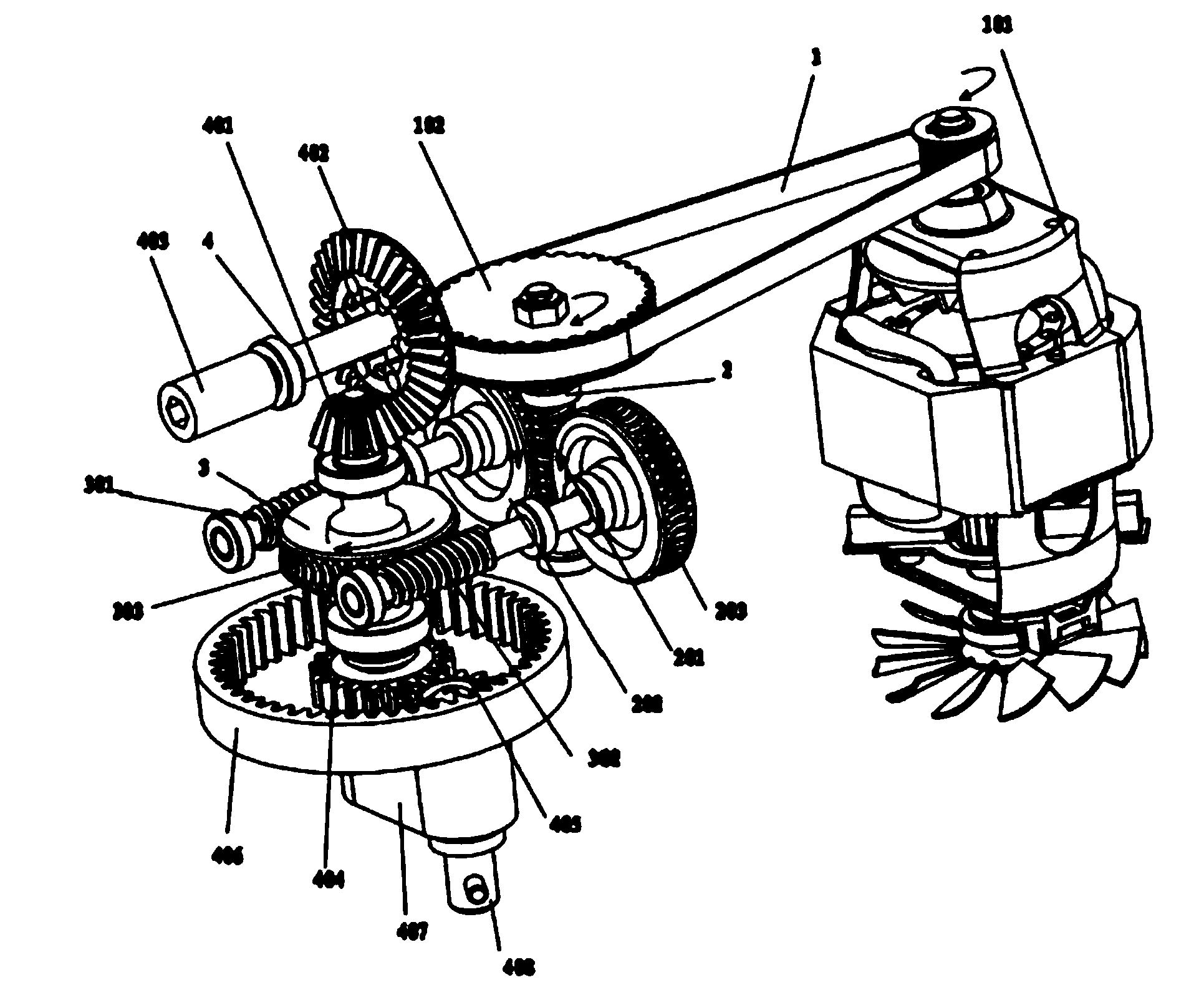
[0036] A worm gear reduction mechanism, such as figure 1 As shown, it includes a drive mechanism 1, a first worm gear transmission mechanism 2 connected to the drive mechanism 1, and a second worm gear transmission mechanism 3. The first worm gear transmission mechanism 2 includes a first drive worm 201, which is connected to the first worm gear 201 respectively. The first worm gear 202 and the second worm gear 203 meshed by the first drive worm 201, one end of the first drive worm 201 is drivingly connected with the drive mechanism 1, and the second worm gear transmission mechanism 3 includes a first drive worm 301, a second worm gear 301 Two transmission worms 302 and the third worm gear 303 meshing with the first transmission worm 301 and the second transmission worm 302 respectively, the first worm gear 202 is drivingly connected with the first transmission worm 301, and the second The turbine 203 is drivingly connected with the second transmission worm 302 , and the third...

Embodiment 2

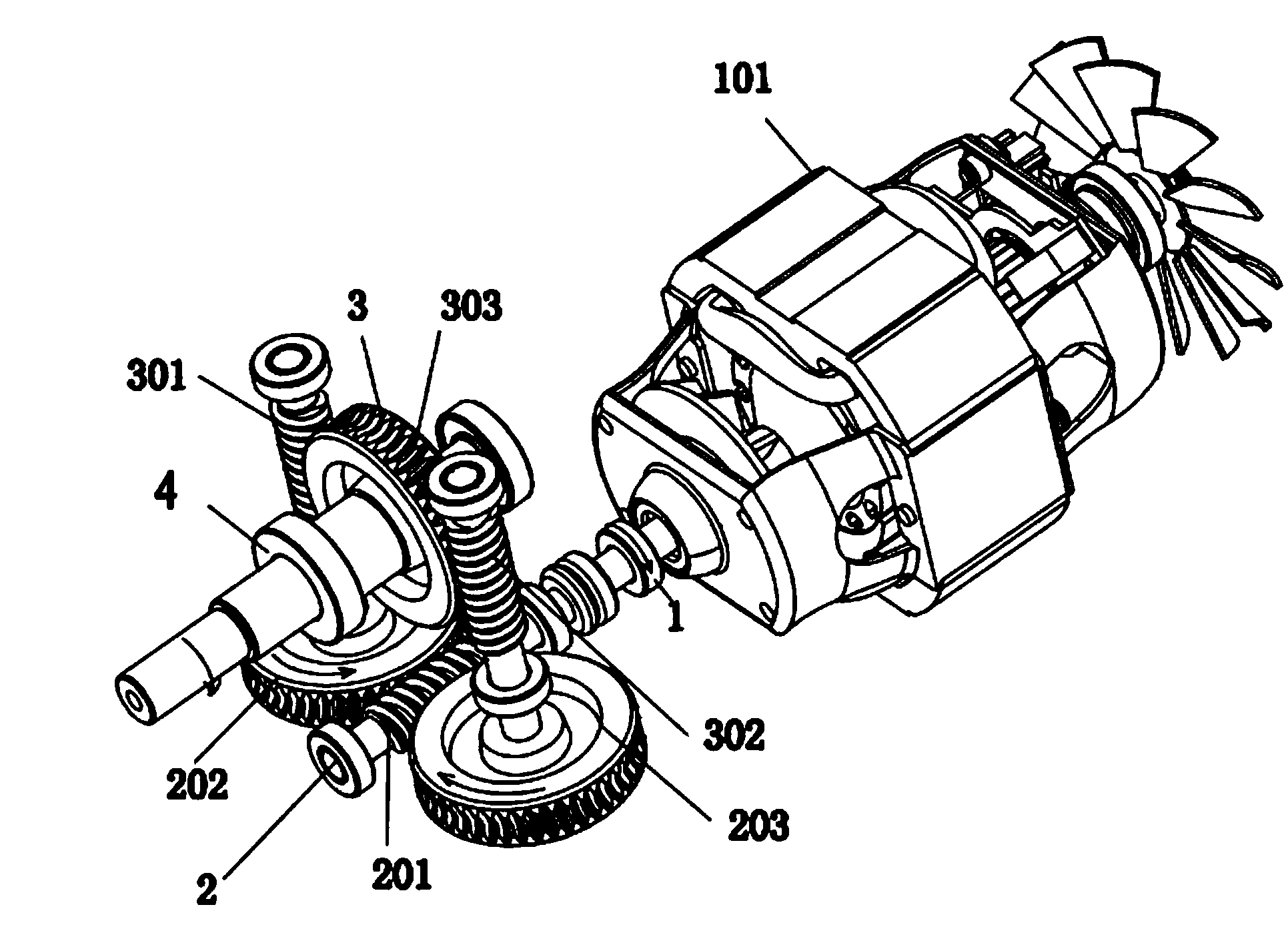
[0045] A kind of worm gear reduction mechanism of the present invention, such as figure 2 As shown, the main technical solutions of this embodiment are basically the same as those of Embodiment 1, and the features not explained in this embodiment are explained in Embodiment 1, and will not be repeated here. The difference between this embodiment and embodiment 1 is:

[0046] The output mechanism 4 is set as a horizontal output mechanism 4, and the horizontal output mechanism 4 is provided with an output main shaft, and one end of the output main shaft is connected with the third turbine 303 through a bearing; the driving mechanism 1 is provided with a driving motor 101, the The motor shaft of the driving motor 101 is drivingly connected with the first driving worm 201 through a bearing.

[0047] Through the horizontal output mechanism, the driving force of the driving mechanism 1 through the first worm gear transmission mechanism 2 and the second worm gear transmission mecha...


PUM


Abstract

A worm and worm gear decelerating mechanism comprises a driving mechanism, a first worm and worm gear transmission mechanism connected with the driving mechanism, and a second worm and worm gear transmission mechanism. The decelerating mechanism is a double-stage progressive worm and worm gear decelerating mechanism. Large speed reduction ratio and low noise are realized by the first worm and worm gear transmission mechanism. High torque transmission and low noise are realized by the second worm and worm gear transmission mechanism. The power transmitted by a driving motor is decomposed by the first worm and worm gear transmission mechanism to a first worm gear and a second worm gear via a first driving worm, and then further delivered to a first transmission worm and a second transmission worm of the second worm and worm gear transmission mechanism. The driving force of the driving motor is delivered to a third worm gear by the first transmission worm and the second transmission worm and finally output by an output mechanism. The decelerating mechanism reduces the impact force of the driving motor and efficiently reduces noise. By double-stage transmission decomposition, the travel is prolonged, the rotating speed is reduced, and the torque and speed reduction ratio are efficiently improved.

Description

technical field [0001] The invention relates to a transmission device, in particular to a worm gear reduction mechanism. Background technique [0002] The worm gear reduction mechanism is a power transmission mechanism that uses the speed converter of the gear to reduce the number of revolutions of the motor (motor) to the desired number of revolutions and obtain a larger torque mechanism. Among the mechanisms currently used to transmit power and motion, the application range of reduction mechanisms is quite wide. [0003] The basic structure of the worm gear reduction mechanism is mainly composed of transmission parts worm gear, shaft, bearing, driving mechanism and output mechanism. The main function of the worm gear is to transmit the motion and power between the two interlaced shafts, and the main function of the bearing and the shaft is to transmit power, run and improve efficiency. [0004] The problems existing in the prior art are: the direct drive transmission, th...

Claims


Application Information

Patent Timeline
Patent Type & Authority Applications(China)
IPC IPC(8): F16H1/22F16H1/28F16H57/028
CPCF16H1/225F16H1/2854F16H37/02F16H57/0006
Inventor 王文雄
Owner SHENZHEN MUREN APPLIANCE
Why Eureka
Try Eureka