Fastening method of T-shaped beam bridge

A technology of girder bridges and beams, which is applied in the field of reinforcement of hinged T-beam bridges, can solve problems such as inability to reinforce, weak hinge joints, and low rigidity, so as to improve durability and service life, enhance connection stiffness, and improve The effect of overall stiffness

Inactive Publication Date: 2009-11-04
BEIJING MUNICIPAL ENG PROFESSIONAL DESIGNINST
View PDF1 Cites 17 Cited by
  • Summary
  • Abstract
  • Description
  • Claims
  • Application Information

AI Technical Summary

Problems solved by technology

[0003] In the prior art, there are two ways to strengthen the hinged T-beam bridge: the first is to replace the old hinged steel plate with a new hinged steel plate, this method does not change the hinge connection relationship between the T-beams , the hinge joint connection is weak, and the overall stiffness of the bridge is not high, so after two or three years of use, the bridge has cracks and needs to be re-strengthened
The second is to recast the bridge deck and increase its thickness. This method increases the thickness of the hinge joint and allows a part of the bridge deck to be combined with the T-beam. The dead load of the T-beam increases a lot, and it does not fundamentally change the stress state of the hinge joint between the T-beams, so the reinforcement effect on the overall bridge is not obvious
The third method is to add multiple steel crossbeams between every two T-beams. Although the steel crossbeams set in this method are connected to the transverse direction, the rigidity of the steel crossbeams is much higher than that of the concrete T-beams. Small, it does not contribute much to the improvement of the transverse stiffness of the whole bridge. In addition, if the connection between the steel beam and the T-beam is improperly handled, the steel beam and the T-beam cannot be simultaneously stressed. In this case, the steel beam is useless and basically Can't play the role of reinforcement
If a pouring joint is cut between the wing plates of the T-beam for pouring the beam, a lot of manpower and material resources will be wasted, and the original structure of the T-beam may be damaged.
In addition, since there is no pouring joint, it is impossible to vibrate the concrete while pouring
Therefore, the method of pouring beams in the construction of new bridges is not suitable for use in the process of strengthening existing beam bridges

Method used


Image

  • Fastening method of T-shaped beam bridge
  • Fastening method of T-shaped beam bridge
  • Fastening method of T-shaped beam bridge

Examples


Embodiment Construction

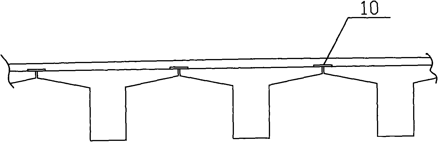
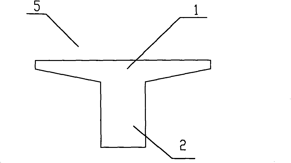
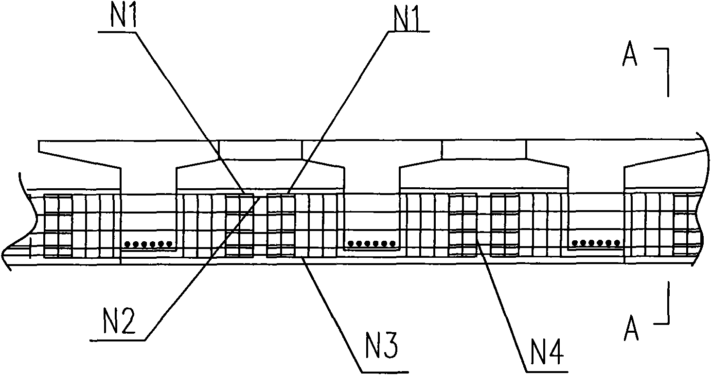
[0040] The reinforcing method of the T-beam bridge of the invention is used for the existing hinge-connected T-beam bridge. The T-beam bridge includes a plurality of T-beams 5 with T-shaped cross-sections, such as figure 2 As shown, the T-beam 5 is composed of a flange 1 located at the horizontal part and a web 2 located at the vertical part. Due to the use of hinge joints, such as figure 1As shown, when the vehicle load acts on the hinge joint, the bending moment is mainly borne by the cast-in-place bridge deck, so the bridge deck at the hinge joint is prone to long longitudinal cracks. At this time, the transverse connection between the T-beams 5 has been greatly Weakened or even failed, it needs to be reinforced. The reinforcement method of the hinged T-beam bridge of the present invention is:

[0041] The process of pouring concrete between the webs 2 of adjacent T-shaped beams 5 to form a concrete beam 4 between the webs 2 of the adjacent T-shaped beams 5, the concret...


PUM


Abstract

The invention relates to a fastening method of a T-shaped beam bridge. The T- shaped beam bridge comprises a plurality of T-shaped beams with the sections being T-shaped; the T-shaped beams comprise a wing plate positioned in a horizontal part and a ventral shield positioned in a vertical part; the fastening method comprises the following steps: reinforcing steel bars are embedded between the ventral shields of the adjacent T- shaped beams and concrete is poured thereinto so that the at least one concrete cross beam along the T-shaped beam span direction is arranged between the ventral shields of the adjacent T- shaped beams. The fastening method of the T-shaped beam bridge solves the problems existing in the prior art fastening the hinge T- shaped beam that the articulation connection is lacking; the jointing position of the articulation seam is easy to weaken and even fails; the whole rigidity of the bridge is not high.

Description

technical field [0001] The invention relates to a reinforcing method of a bridge, in particular to a reinforcing method of a hinged T-beam bridge. Background technique [0002] At present, among the existing T-beam bridges built in my country, most of the transverse connections between T-beams are hinge connections, and the hinge connections are realized by setting hinged steel plates between adjacent T-beams ( See figure 1 ), when using the hinge connection, because it only transmits shear force, the bending moment is mainly borne by the cast-in-place bridge deck when the vehicle load acts on the hinge joint, while a large number of active hinged T-beam bridges in China have cast-in-place bridge decks The thickness of the T-beam is small, so the bridge deck at the hinge joint is prone to long longitudinal cracks, which not only affects the traffic, but also weakens or even fails the transverse connection between the T-beams, so that the load is mainly caused by the T-beam w...

Claims


Application Information

Patent Timeline
Patent Type & Authority Applications(China)
IPC IPC(8): E01D22/00
Inventor 刘锋王连红刘四田陈桂英郝春伟
Owner BEIJING MUNICIPAL ENG PROFESSIONAL DESIGNINST
Why Eureka
Try Eureka