Plastic liner protruding-type socket steel ring concrete top tube

A technology of socket steel ring and concrete pipe, applied in the direction of pipes, rigid pipes, pipes/pipe joints/pipes, etc., can solve the problems of high transmission power requirements, affecting the quality of the process engineering, poor impermeability, etc., to improve the engineering quality , The effect of improving economic efficiency and good impermeability

Inactive Publication Date: 2009-11-04
TIANJIN WATERLINE PIPELINE ENG CO LTD
View PDF0 Cites 2 Cited by
  • Summary
  • Abstract
  • Description
  • Claims
  • Application Information

AI Technical Summary

Problems solved by technology

At present, the main structure of concrete pipe jacking is as follows: the concrete pipe core is embedded with a steel skeleton pipe cage, which is made of two coaxial cylindrical steel skeletons fixed by erecting bars, and one end of the concrete pipe core The socket end of the fixed steel socket is integrally poured with concrete. Although this type of concrete pipe jacking can be used for jacking construction, it still has the following defects: the socket end of the concrete pipe core is formed by one-time pouring of concrete, which is easy to be carried out during jacking. The damage during the construction collision will lead to the occurrence of grout leakage, which will affect the construction process and project quality, and the concrete jacking pipe used for jacking construction has poor impermeability. At present, the steel cylinder is placed in the core of the existing concrete jacking pipe To solve the problem of poor impermeability, although it can achieve better impermeability effect, the cost is high, especially today when the price of steel is rising day by day. In addition, the friction coefficient of the liquid transported on the inner wall of the concrete is relatively large, and the liquid transported over a long distance Pumps with larger power are often required in the medium, which requires higher transmission power.

Method used


Image

  • Plastic liner protruding-type socket steel ring concrete top tube
  • Plastic liner protruding-type socket steel ring concrete top tube
  • Plastic liner protruding-type socket steel ring concrete top tube

Examples


Embodiment Construction

[0020] The present invention will be further described in detail below through the specific examples, the following examples are only descriptive, not restrictive, and cannot limit the protection scope of the present invention with this.

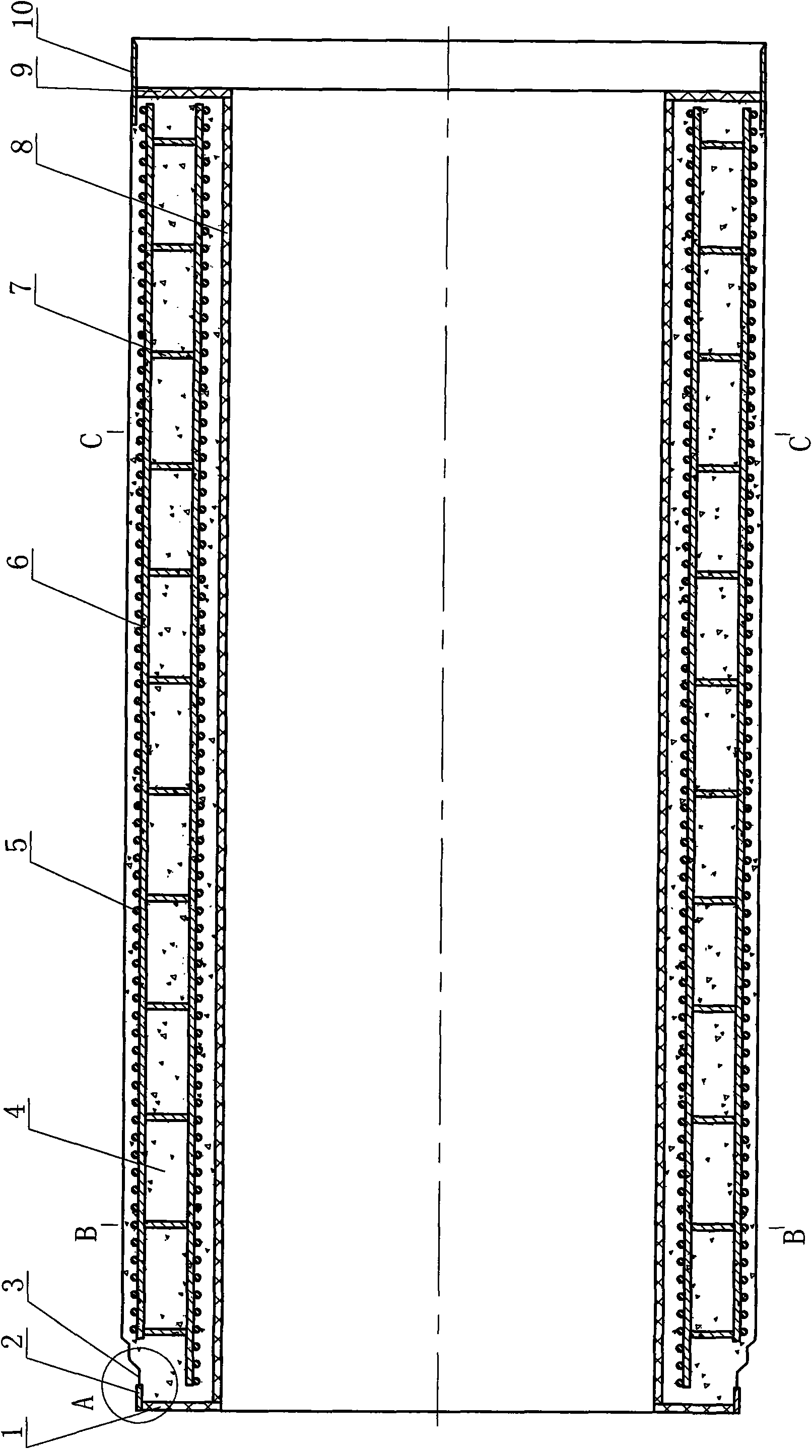
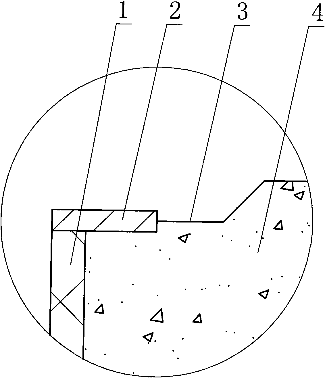
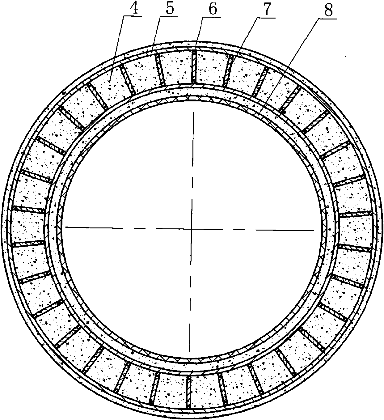
[0021] The plastic-lined protruding socket steel ring concrete jacking pipe is composed of a steel socket 10, a cylindrical steel skeleton pipe cage and a concrete pipe core 4. The steel socket is fixed on one end of the concrete pipe core, and the cylindrical steel skeleton The pipe cage is coaxially embedded in the concrete pipe core. The cylindrical steel skeleton pipe cage is composed of two coaxial cylindrical steel cages welded by the circumferential steel bars 5 and the longitudinal steel bars 6 and welded coaxially through the vertical bars 7. Formed cylindrical steel bar skeleton pipe cage form, (as shown in the accompanying drawing of this embodiment), this cylindrical steel bar skeleton also can be the cylindrical steel bar cage of...


PUM


Abstract

The invention relates to a plastic liner protruding-type socket steel ring concrete top tube comprising a steel bell, a cylindrical reinforcement frame tube cage and a concrete tube core. The steel bell is fixedly mounted at one end of the concrete tube core, and the cylindrical reinforcement frame tube cage is coaxially embedded in the concrete tube core; a socket steel ring is coaxially fixedly mounted on the outer wall of the socket end of the concrete tube core, the outer wall diameter of the socket steel ring is larger than the socket outer wall diameter of the concrete tube core so as to radially form a groove between a socket of the concrete tube core and the concrete tube core, and a plastic liner cylinder is coaxially fixedly mounted on the inner wall of the concrete tube core. The plastic liner protruding-type socket steel ring concrete top tube has simple structure, scientific and reasonable design, firm socket, better impermeability and corrosion resistance, lower raw material cost and small inside tube wall coefficient of friction resistance.

Description

technical field [0001] The invention relates to concrete pipes, in particular to a plastic-lined protruding socket steel ring concrete jacking pipe. Background technique [0002] Among concrete pipes, concrete pipe jacking is widely used, especially in the occasions where slotting is not possible. At present, the main structure of concrete pipe jacking is as follows: the concrete pipe core is embedded with a steel skeleton pipe cage, which is made of two coaxial cylindrical steel skeletons fixed by erecting bars, and one end of the concrete pipe core The socket end of the fixed steel socket is integrally poured with concrete. Although this type of concrete pipe jacking can be used for jacking construction, it still has the following defects: the socket end of the concrete pipe core is formed by one-time pouring of concrete, which is easy to be carried out during jacking. The damage during the construction collision will lead to the occurrence of grout leakage, which will af...

Claims


Application Information

Patent Timeline
IPC IPC(8): F16L9/153F16L58/10F16L25/10
Inventor 赵斌张亮
Owner TIANJIN WATERLINE PIPELINE ENG CO LTD
Why Eureka
Try Eureka