

LED backlight module
A technology of backlight module and light source, applied in optics, light guide, light source and other directions, can solve the problems of dark area and large mixing distance, and achieve the effect of saving cost, reducing light mixing distance and reducing the number of use.
- Summary
- Abstract
- Description
- Claims
- Application Information
AI Technical Summary
Problems solved by technology
Method used
Image

Examples
Embodiment 1
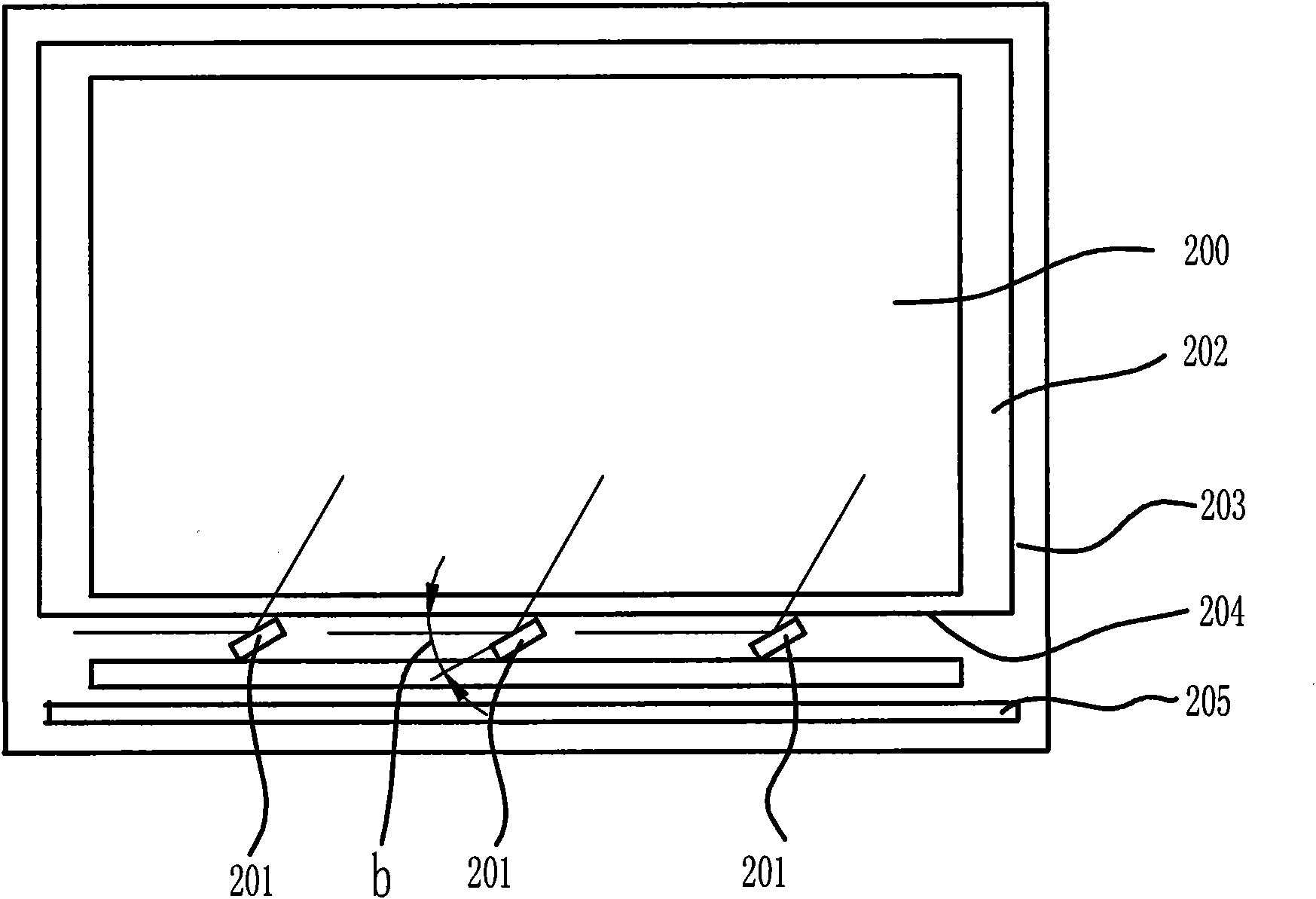
[0033] figure 2 It is a top view of the structure of the first embodiment of the present invention, as figure 2 As shown, the backlight module 200 includes at least one LED light source 201, a reflector 205, a rectangular light guide plate 202, a frame 203 and a set of optical films (not shown). The light guide plate 202 has a light incident surface 204 , and the reflection surface of the reflection device 205 is disposed opposite to the light incident surface 204 of the light guide plate 202 . The LED light source 201 is arranged between the reflection device 205 and the light incident surface 204 of the light guide plate 202, and the light output surface of the LED light source 201 is inclined towards the light incident surface 204 of the light guide plate 202 and arranged at a certain angle b, and the angle b is greater than 0 ° and less than 90°.
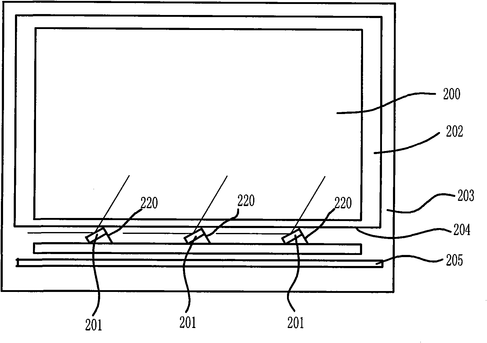
[0034] image 3 yes figure 2 Schematic diagram of the improved arrangement of the LED light source 201 in the middle, s...
Embodiment 2
[0038] Such as Figure 8 As shown, the backlight module of the present invention includes: at least one LED light source 310, the appearance of the LED light source 310 has a light output surface inclined towards the light incident surface 204 of the light guide plate 202; a reflection device 205, a light guide plate 202, a frame 203 and a set of optical films (not shown). The LED light source 310 is disposed between the reflection device 205 and the light incident surface 204 of the light guide plate 202 , and the light output surface of the LED light source 310 is inclined toward the light incident surface 204 of the light guide plate 202 . In this embodiment, the LED light source 310 has a trapezoidal shape in cross section.
[0039] Figure 9 yes Figure 8 Another improved structure schematic diagram of the LED light source 310 in the middle, such as Figure 9As shown, the appearance of the LED light source 320 with this structure has a light-emitting surface on an obl...
PUM
 Abstract
Description
Claims
Application Information