Luminescence unit circuit board module

A light-emitting unit and circuit board technology, which is applied to circuit layout, lighting devices, components of lighting devices, etc., can solve problems such as difficult maintenance, inability to insert traditional lamp caps, and difficult assembly of light-emitting modules, so as to reduce the peripheral size and facilitate the The effect of assembly

Inactive Publication Date: 2009-11-04
简世忠
View PDF0 Cites 0 Cited by
  • Summary
  • Abstract
  • Description
  • Claims
  • Application Information

AI Technical Summary

Problems solved by technology

[0003] The above-mentioned light-emitting module is not easy to assemble and not easy to maintain
During assembly, a welding procedure is required, and when the light-emitting unit 12 fails, when the light-emitting unit is to be replaced, the solder must be removed before replacement
And the plane of this common circuit board 15 is perpendicular to the optical axis of the light-emitting unit. When the periphery of the product needs to be reduced, for example, when it is to be placed in a traditional lamp holder to replace a traditional light bulb, the design of this circuit board 15 will not be able to be placed traditional lamp holder

Method used


Image

  • Luminescence unit circuit board module
  • Luminescence unit circuit board module
  • Luminescence unit circuit board module

Examples


Embodiment Construction

[0023] The present invention will be further elaborated below in conjunction with the accompanying drawings and specific embodiments. These examples should be understood as only for illustrating the present invention but not for limiting the protection scope of the present invention. After reading the contents of the present invention, those skilled in the art can make various changes or modifications to the present invention, and these equivalent changes and modifications also fall within the scope defined by the appended claims of the present invention.

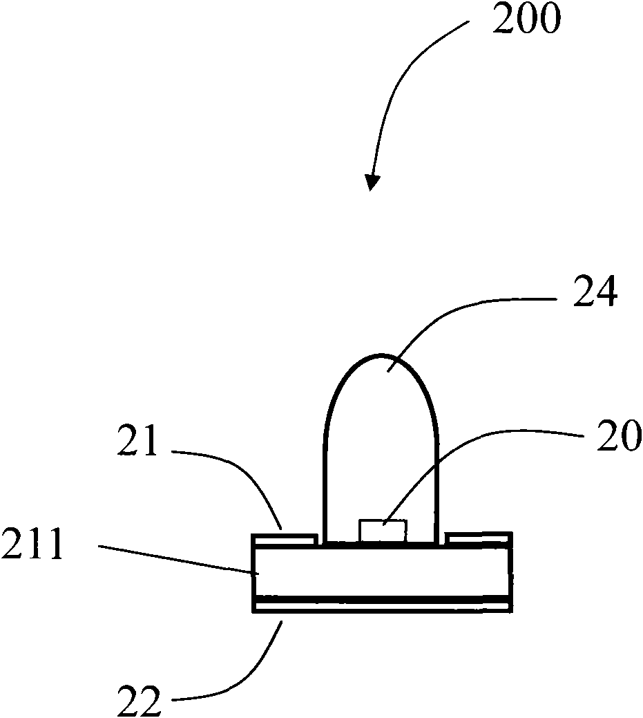
[0024] Such as figure 2 As shown, the light emitting unit 200 used in the following embodiments of the present invention includes a light emitting chip 20 and has a first electrode electrically coupled to the upper metal plate 21 ; the light emitting chip 20 has a second electrode electrically coupled to the lower metal plate 22 . There is an insulating material 211 between the upper metal plate 21 and the lower metal pla...


PUM


Abstract

The invention discloses a luminescence unit circuit board module which comprises a luminescence unit circuit board and a parallel-metal base. Each luminescence unit is provided with a substrate formed by stacking an upper metal insulating material and a lower metal, and the parallel metal base comprises a first metal board and a second metal board; the first metal board is electrically coupled to the upper metal and provided with a first metal pin, and the second metal board is electrically coupled to the lower metal and provided with a second metal pin; the circuit board comprises a first electric contact region and a second electric contact region, the first electric contact region is electrically coupled to the first metal pin, and the second electric contact region is electrically coupled to the second metal pin. The parallel-metal base of the luminescence unit circuit board module is spliced with the circuit board in a plug-in mode so as to be convenient to assembly, maintain and replace the product.

Description

technical field [0001] The invention relates to a light-emitting unit circuit board module, in particular to a light-emitting module provided with parallel metal seats for the light-emitting unit to be placed on the circuit board in a plug-in manner. Background technique [0002] Common lighting modules such as figure 1 As shown, the light-emitting unit 12 has a plane area where the light-emitting chip 10 is arranged on the first metal pin 141, and the metal pin 141 extends downward; the light-emitting chip 10 has a bottom surface electrode electrically coupled to the first metal pin 141; the light-emitting chip 10 has a surface electrode , electrically coupled to the second metal pin 142 by the metal line 13 . The circuit board 15 has a plated through hole 151 and the circuit 152 is connected to the power supply terminal. The first metal pin 141 and the second metal pin 142 are inserted into the corresponding plated through hole 151 on the circuit board 15, and then the fi...

Claims


Application Information

Patent Timeline
Patent Type & Authority Applications(China)
IPC IPC(8): F21V23/00F21V23/06
Inventor 简世忠
Owner 简世忠
Why Eureka
Try Eureka