Automatic laser repair method

A laser and automatic technology, applied in nonlinear optics, instruments, optics, etc., can solve the problems of reduced repair success rate, increased manufacturing cost, and increased operation time, so as to reduce the chance of manual operation errors and improve the repair success rate , the effect of shortening the time

Inactive Publication Date: 2009-11-04
CENTURY DISPLAY (SHENZHEN) CO LTD
View PDF0 Cites 8 Cited by
  • Summary
  • Abstract
  • Description
  • Claims
  • Application Information

AI Technical Summary

Problems solved by technology

[0015] As far as the above process is concerned, although this non-automatic or semi-automatic repair process can still achieve the purpose of repairing defects, there are some problems. For example, the operator needs to manually input the same laser path repea

Method used


Image

  • Automatic laser repair method
  • Automatic laser repair method
  • Automatic laser repair method

Examples


Example Embodiment

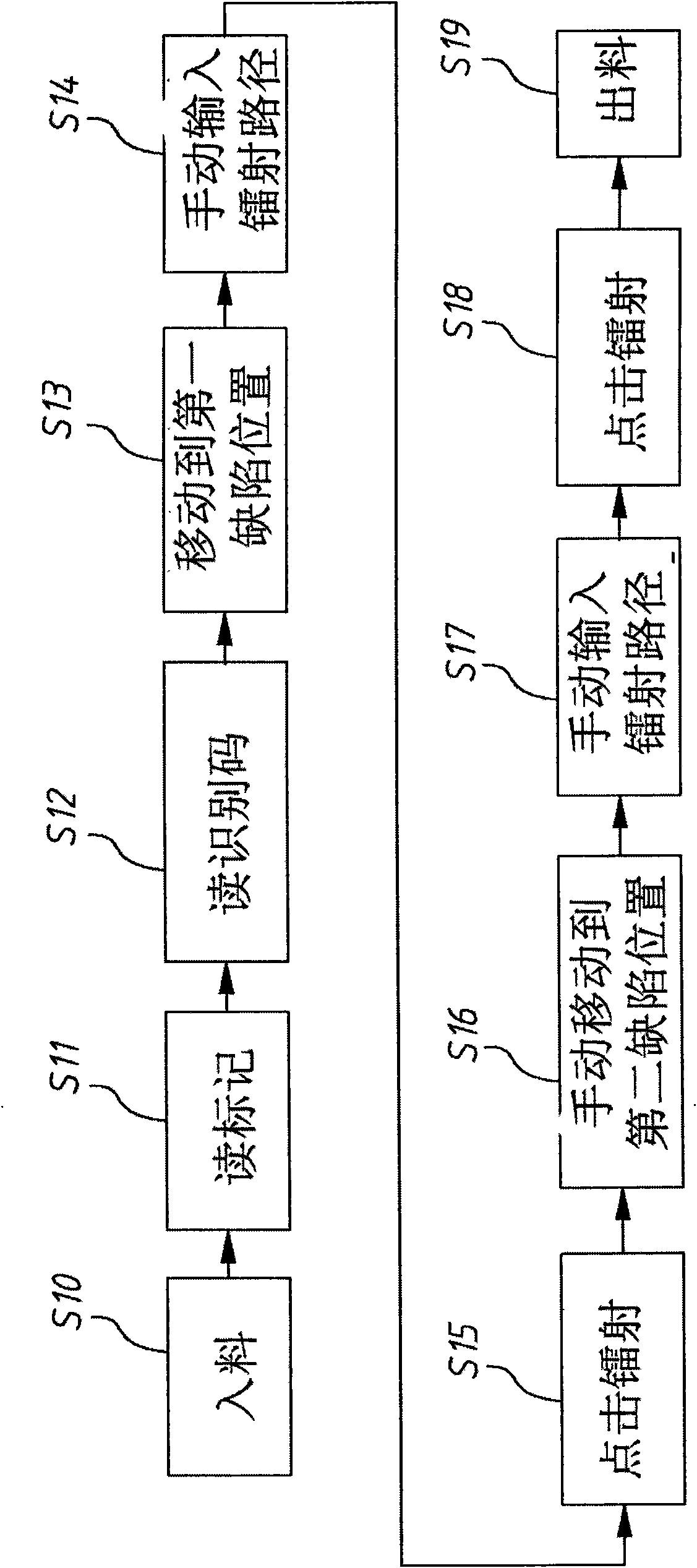
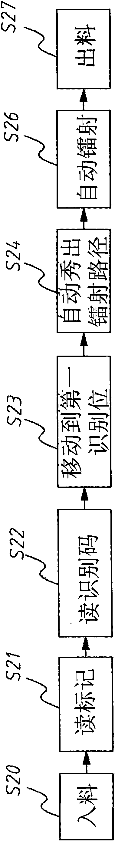
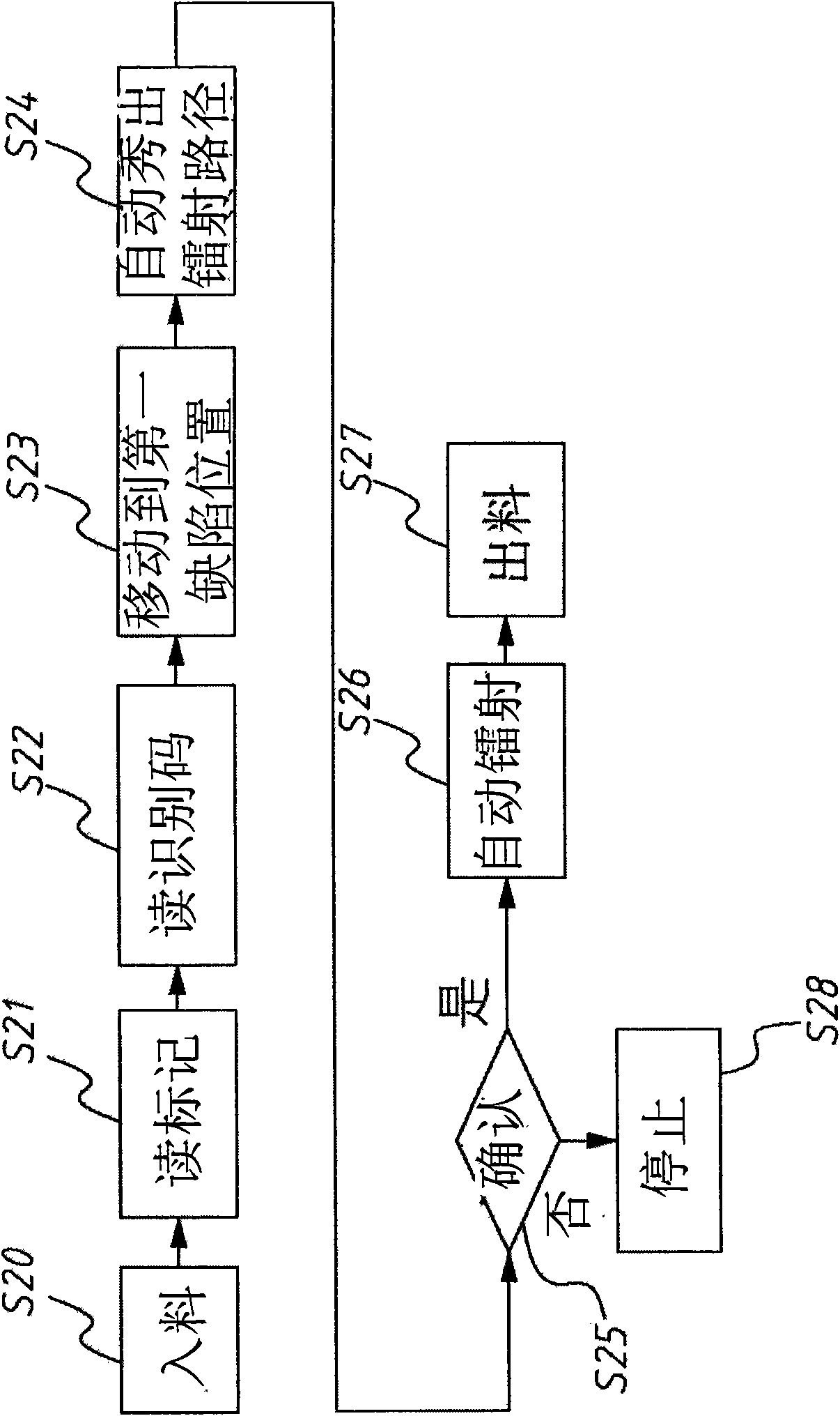
[0031] In the assembly (Cell) process, automatic laser repair is to solve the problems existing in the previous technology, thereby shortening the time required for the laser repair process (Tact time), thereby increasing production capacity, and reducing the chance of manual operation errors, To improve the repair success rate. Below is a display panel as the object to be repaired, and the technology of the present invention is described in detail according to the embodiment.

[0032] Before laser repair, the process of defect detection and classification will be carried out;

[0033] In detail, in the lighting test process, the defect code (Defect code) and defect address (Defect address) on the display panel will be reported to the inspection system, and a defect code corresponds to a defect location;

[0034] Continuing with the defect classification (Sorting) of the laser repair front station, various defect panels are classified, that is, the display panels with defects...


PUM


Abstract

The invention mainly relates to a Laser repair method, in particular to an automatic laser repair method for repairing defects generated during manufacturing a display panel. The method comprises the following steps: at least one panel to be repaired is provided, and the panel to be repaired has at least one defect and is processed by classification of defects to have the defect of only one laser path; according to a defect position, a laser head automatically moves to the defect position and selects a corresponding laser prescription; and a laser path is automatically displayed according to the laser prescription, and the only one laser path is utilized to automatically laser the defect for repairing. The automatic laser repair technology can effectively shorten the Tact time required by a laser repair processing procedure so as to improve the productivity, reduce the opportunity of manual operation errors and improve the repair success ratio.

Description

technical field [0001] The present invention mainly relates to a laser repair method, in particular to an automatic laser repair method for repairing defects generated in the manufacture of display panels. Background technique [0002] In the liquid crystal display panel (LCD) manufacturing process, from the front-end array (Array) process, assembly (Cell) process, until entering the module (Module) process, the liquid crystal display panel has completed most of the chemical, physical processing and material combination. The procedures and flaw detection are carried out to ensure the quality. Next, the driver IC and circuit board are installed in the module manufacturing process, and then assembled with the backlight to form a liquid crystal module. [0003] Although the liquid crystal display panel technology is quite mature now, it is inevitable that there will be defects in the panel production process. These defects will cause abnormal bright spots on the display. If the...

Claims


Application Information

Patent Timeline
IPC IPC(8): G02F1/13
Inventor 庄涂城游学文
Owner CENTURY DISPLAY (SHENZHEN) CO LTD
Why Eureka
Try Eureka