Method and device for the assembly and disassembly of a preplasticizing spindle

A technology for worms and injection molding machines, which is applied in the field of plasticizing worms, and can solve the problems of installation and disassembly requiring a lot of time and cost

Inactive Publication Date: 2009-11-04
NETABTAL MASCHEN
View PDF1 Cites 8 Cited by
  • Summary
  • Abstract
  • Description
  • Claims
  • Application Information

AI Technical Summary

Problems solved by technology

Clamp connections are cheaper, but also have disadvantages in terms of centering
[0008] The solutions of the prior art are disadvantageous

Method used


Image

  • Method and device for the assembly and disassembly of a preplasticizing spindle
  • Method and device for the assembly and disassembly of a preplasticizing spindle
  • Method and device for the assembly and disassembly of a preplasticizing spindle

Examples


Embodiment Construction

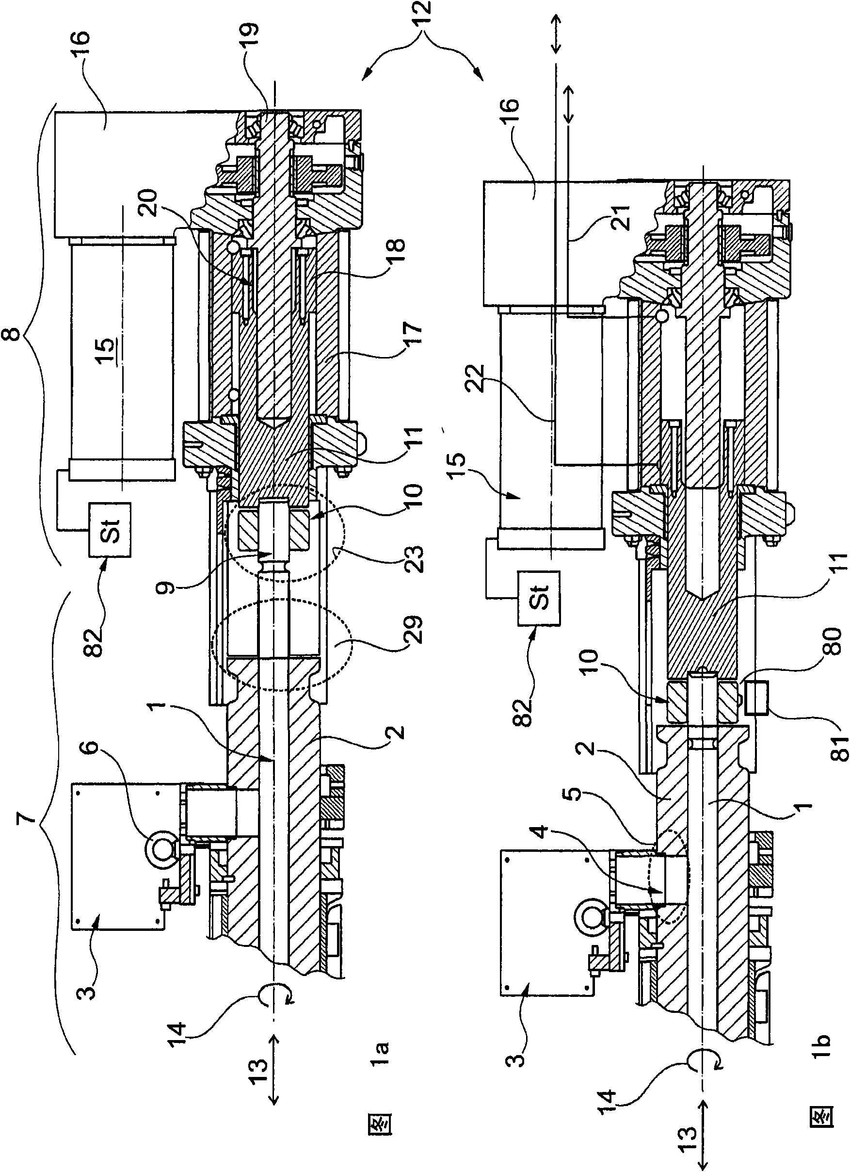
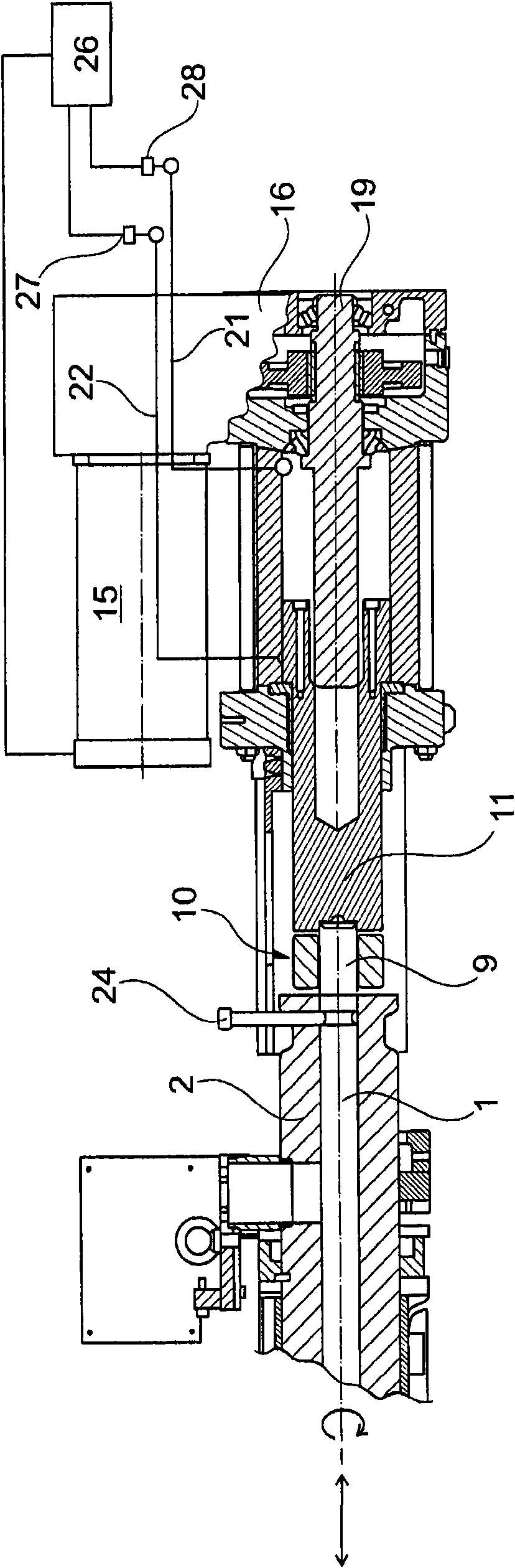
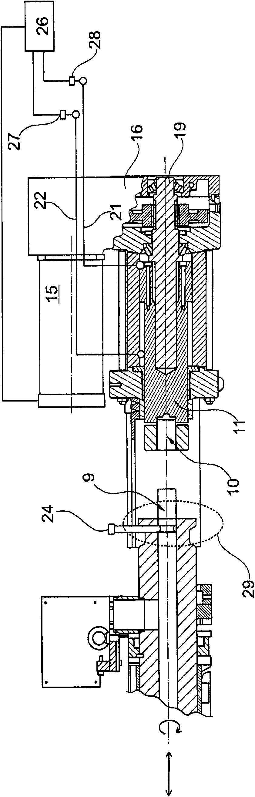
[0046] Refer below Figure 1a and 1b . These two figures show the region of the coupling mechanism in the retracted position of the plasticizing worm 1 ( Figure 1a ) and the case of (1b) in its frontmost position. The plasticizing cylinder 2 is shown on the left side of the figure together with the holding structure 3 for the pellet supply funnel. The still dry pellets are fed into the intake area of ​​the plasticizing screw 1 via the feed opening 4 . A fastening ring 6 is shown here for mounting and dismounting the plasticizing device 7 by means of a machine crane, not shown. In the rear part, the plasticizing worm 1 has a coupling rod 9 which is inserted into a clamping coupling 10 of the drive end 11 of the injection unit 8 . The drive unit 12 is designed for two types of movement of the plasticizing screw 1 , namely a linear movement according to arrow 13 and a rotational movement according to arrow 14 . The rotational movement is produced by a drive motor 15 and a tr...


PUM


Abstract

The invention relates to a method and a device for the assembly and disassembly of the preplasticizing spindle (1) of a ram or drive end (11) of a worm drive system of an injection molding machine by means of a clamp coupling (10). The worm drive system is designed for a controlled linear and rotary movement of the preplasticizing spindle (1). The coupling occurs by means of clamping agents which are preferably in the form of mechanical clamp coupling (10), wherein the rotary driving power and the worm return force are transferred via frictional engagement, and the axial injection force is transferred via an end stop. The assembly and disassembly procedure is supported by being controlled by the worm drive system. The preplasticizing spindle (1) can also be developed and coupled or decoupled as a heat-shrinkage connection or as a hydraulic tension system (23), wherein the preplasticizing spindle (1) is introduced during coupling to the end stop.

Description

technical field [0001] The invention relates to a method for mounting and dismounting a plasticizing worm of a piston or drive end (Antriebsstummel) of a worm drive of an injection molding machine by means of a releasable coupling, wherein the worm drive is designed for the The controlled linear and rotary motion of the plasticizing worm is described. [0002] Furthermore, the invention relates to a device for mounting and dismounting a piston or a drive-side plasticizing worm of a worm drive system of an injection molding machine by means of a releasable coupling. Background technique [0003] The core component of the injection molding machine consists of the entire injection unit on the injection side, which in turn includes the injection unit and the drive system for the plasticizing worm as well as the plasticizing unit with the plasticizing worm. The entire spray assembly is mounted displaceably by means of a special drive, so that the spray tip of the plasticizing de...

Claims


Application Information

Patent Timeline
IPC IPC(8): B29C45/17
CPCB29C45/176B29C45/50
Inventor R·温曼P·温津M·扎纳
Owner NETABTAL MASCHEN
Why Eureka
Try Eureka