Floodlight with tiltable beam

A floodlight and light beam technology, applied in the field of floodlights, can solve problems such as complex and complex mechanical devices

Inactive Publication Date: 2009-11-04
KONINK PHILIPS ELECTRONICS NV
View PDF6 Cites 11 Cited by
  • Summary
  • Abstract
  • Description
  • Claims
  • Application Information

AI Technical Summary

Problems solved by technology

Also, orienting the beam correctly is a complex operation because the mechanics used to position the array are complex

Method used


Image

  • Floodlight with tiltable beam
  • Floodlight with tiltable beam
  • Floodlight with tiltable beam

Examples


Embodiment Construction

[0020] In this specification, the beam width is measured according to the full-width half-maximum method (FWHM), which is well known in the art.

[0021] The lens array is composed of multiple lenses, and the optical axes of the lenses are two-two parallel. The focal plane of the lens array is the plane perpendicular to the optical axis of the lenses of the array and passing through the focal point of at least one lens of the lens array. When it is described that two lens arrays are parallel, it means that the focal plane of the first lens array is parallel to the focal plane of the second lens array.

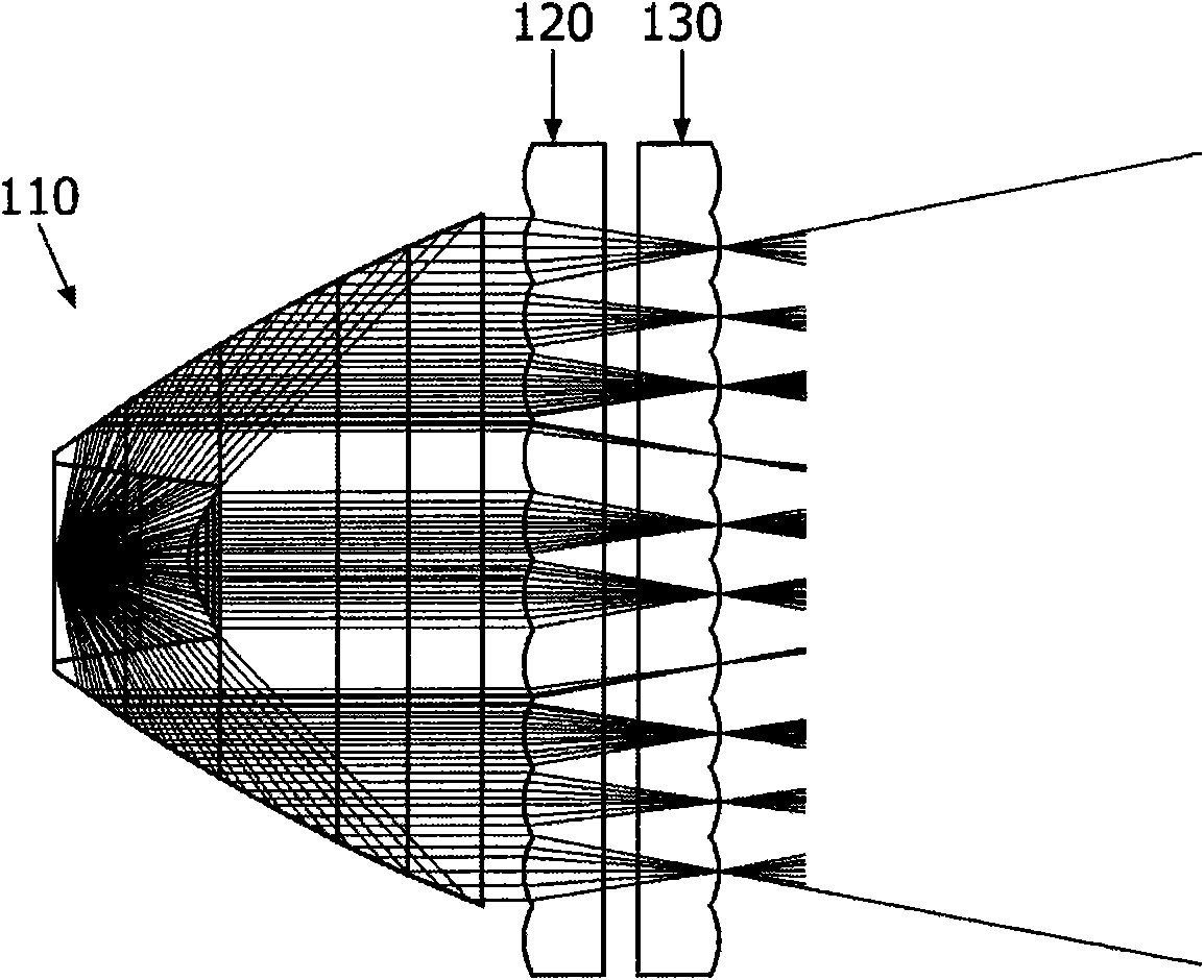
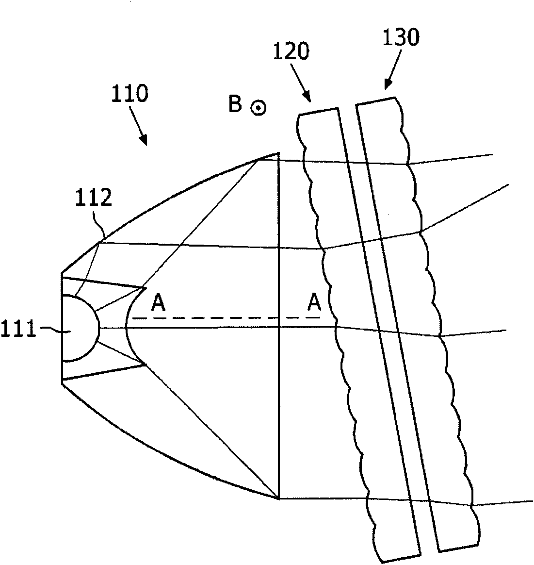
[0022] exist Figure 1a with 1b Described in is a luminaire according to a first embodiment of the present invention. This luminaire comprises means 110 for producing a parallel light beam. The general direction of the parallel beam is AA. The first lens array 120 is positioned on the path of the parallel light beams. The first lens array 120 includes a plurality of conve...


PUM


Abstract

The present invention discloses a floodlight comprises means (110) for generating a parallel beam having a general direction (AA), a first convergent lenses array (120) for generating a plurality of convergent beams from said parallel beam, and a second lenses array (130) parallel to and integral with said first lenses array. The floodlight further comprises means for rotating simultaneously said first and second lenses arrays about an axis perpendicular to the general direction of the parallel beam.

Description

technical field [0001] This invention relates to floodlights intended for use in various lighting applications. The invention is particularly relevant to stage lighting, facade lighting, accent lighting. Background technique [0002] In the field of lighting, various kinds of light beams are often required. On the one hand, when the façade is to be illuminated, a wide beam is required so that the entire façade is illuminated. On the other hand, in order to illuminate only the details of the exterior, a narrow beam may be required. Various floodlights are used for this purpose. [0003] Furthermore, floodlights are often inserted into recessed cavities, such as in roads, in sidewalks, or in walls. Therefore, the beam is correctly pointed at the unit to be illuminated. [0004] International patent publication WO2005 / 093319 discloses a floodlight in which the light beam provided by light emitting diodes (LEDs) can be tilted. The luminaire comprises a first lens array arr...

Claims


Application Information

Patent Timeline
Patent Type & Authority Applications(China)
IPC IPC(8): F21S8/00F21W131/10F21V14/06
CPCG02B3/0068F21V14/06G02B3/0043G02B3/0056F21W2131/10G02B3/005G02B3/0062G02B26/0875
Inventor D·福尔尼尔M·朱弗里厄
Owner KONINK PHILIPS ELECTRONICS NV
Why Eureka
Try Eureka