
Hinge device

A technology of hinge device and hinge frame, which is applied to hinges with pins, door/window fittings, hinge plates, etc. It can solve the problems of unsatisfactory opening and closing rotation, large displacement of the rotation center, and limited use range, so as to save corners space, reduce workload, and use a wide range of effects

Inactive Publication Date: 2012-08-29
JIANGSU UNIV OF SCI & TECH
View PDF5 Cites 0 Cited by
  • Summary
  • Abstract
  • Description
  • Claims
  • Application Information

AI Technical Summary

Problems solved by technology

Because there is a central mandrel in this hinge, the central mandrel occupies the spatial position at the corner of the movable member and the fixed member, so that this hinge cannot meet the opening and closing rotation of some special requirements, thus limiting its scope of use
Another type of hinge is a planar four-bar linkage hinge without a central mandrel. Through the movement of the four-bar linkage, the flip of the movable member can be realized. Although this kind of hinge can realize the rotation of the center of rotation without the central shaft, the displacement of the center of rotation It is too large to be used in components that require a relatively fixed center of rotation

Method used


Image

  • Hinge device
  • Hinge device
  • Hinge device

Examples


Embodiment Construction

[0015] The present invention will be further described below in conjunction with the accompanying drawings and the embodiments of the manual folding machine.

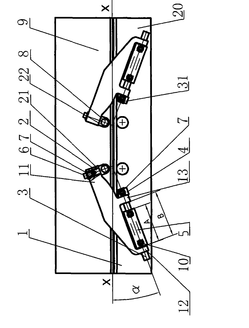
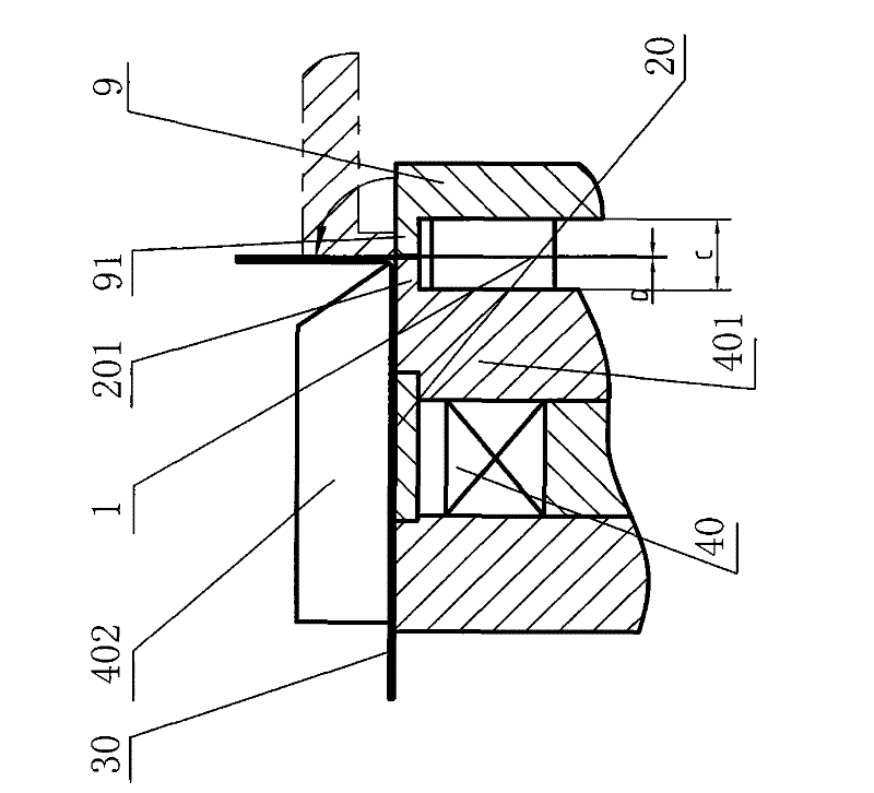
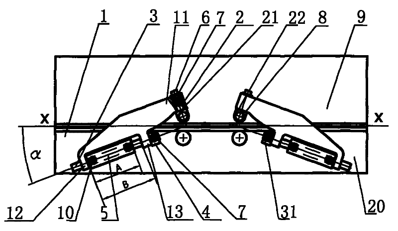
[0016] Such as figure 1 As shown, the present invention includes a hinge frame 1, a first mandrel 2, a second mandrel 3, a fixed seat 4, and a limit seat 5 symmetrically arranged on both sides of the fixed member; the hinge frame 1 of this embodiment is the lower side The plate-shaped member provided with two legs 12, 13 can be processed by steel plate cutting or directly cast. The first mandrel 2 is a combination structure in which the upper end is a round shaft end 21 and the lower end is a limiting square head 22. When assembling, the upper end 11 of the hinge frame 1 is first set on the round shaft end 21 of the first mandrel 2, and then the The screw 6 and the washer 7 are fixedly connected to the round shaft end 21 of the first mandrel 2, so that the hinge frame 1 forms a flexible connection with the round shaft ...


PUM


Abstract

The invention discloses a hinge device, which comprises a hinge mount, a first mandrel, a second mandrel, a permanent seat and a limiting seat symmetrically arranged at two sides of a stander, whereinthe upper end of the hinge mount is sleeved on the first mandrel and is movably connected with the upper end of the first mandrel through a fastening piece, and the lower end of the first mandrel isfixed on a movable component through the fastening piece; the upper end of the second mandrel is supported in the limiting seat, the middle part of the second mandrel supported in the permanent seat,a plurality of fastening pieces pass through the permanent seat and the second mandrel and are fixedly connected with a fixed component respectively; the lower end of the hinge mount is sleeved on thesecond mandrel and is movably connected with the second mandrel; and axial lines of the first mandrel and the second mandrel are vertical to each other. The hinge device solves the rotation without arotating shaft in a hinge rotating center, and simultaneously controls the inclined angle of a second rotating shaft to control the displacement of the rotating center of the hinge mount, changes thestress direction of a hinge, and improves the working strength of the hinge.

Description

technical field [0001] The invention relates to a movable connection device between two components, in particular to a connection device capable of opening and closing in space between two components, and belongs to the technical field of mechanical connection devices. Background technique [0002] Hinges are often used to connect movable and fixed components, such as doors and door frames, box covers and boxes. There are usually two types of conventional hinges. One is a hinge with only one revolving pair. The hinge is formed by the revolving pair of the mandrel and the sleeve. The center of rotation is determined, and the center of rotation is the center of the mandrel. Because there is a central mandrel in this hinge, the central mandrel occupies the spatial position at the corner of the movable member and the fixed member, so that this hinge cannot meet the opening and closing rotation of some special requirements, thus limiting its scope of use. . Another type of hing...

Claims


Application Information

Patent Timeline
Patent Type & Authority Patents(China)
IPC IPC(8): E05D3/06E05D5/02
Inventor 凌有临冯学东冯拥军朱东昌
Owner JIANGSU UNIV OF SCI & TECH
Learn More