

Radiating method of LED radiator and radiator for implementing same
A technology of LED heat sink and heat dissipation method, which is applied in the direction of electric solid-state devices, semiconductor devices, lighting and heating equipment, etc. It can solve the problems of accelerating the speed of LED light decay, accelerating the aging of devices, and shortening the service life, so as to solve the problem of heat dissipation , prolong the service life and reduce the speed of light decay
Active Publication Date: 2011-01-05
DONGGUAN PERFECT SCI & TECH
View PDF0 Cites 1 Cited by
- Summary
- Abstract
- Description
- Claims
- Application Information
AI Technical Summary
Problems solved by technology
Excessive chip temperature will bring many problems, such as accelerating device aging, speeding up LED light decay, shortening service life, and even causing chip burnout; how to effectively solve heat dissipation has become the most urgent problem for high-power LED lamps. question
Method used
View moreImage
Smart ImageViewing Examples

Examples
Embodiment
Login to View More PUM
 Abstract
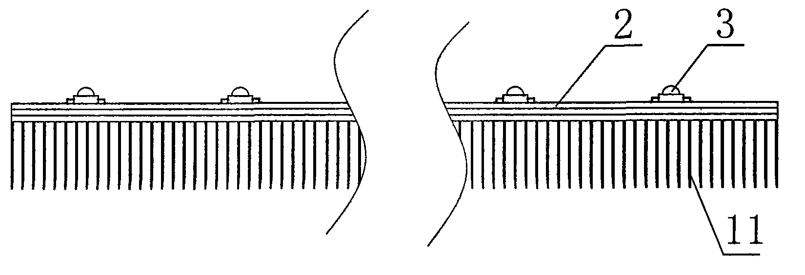
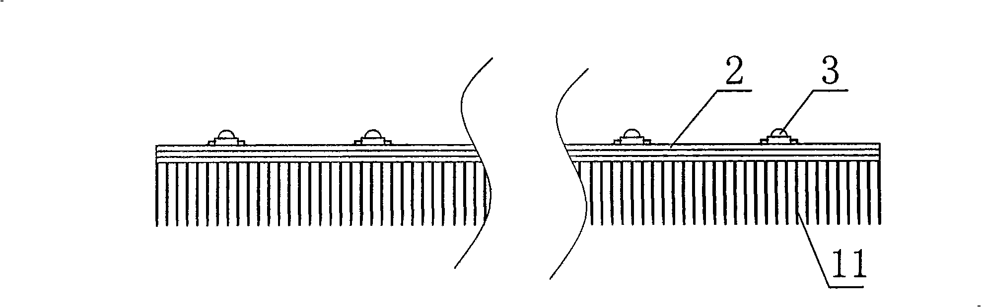
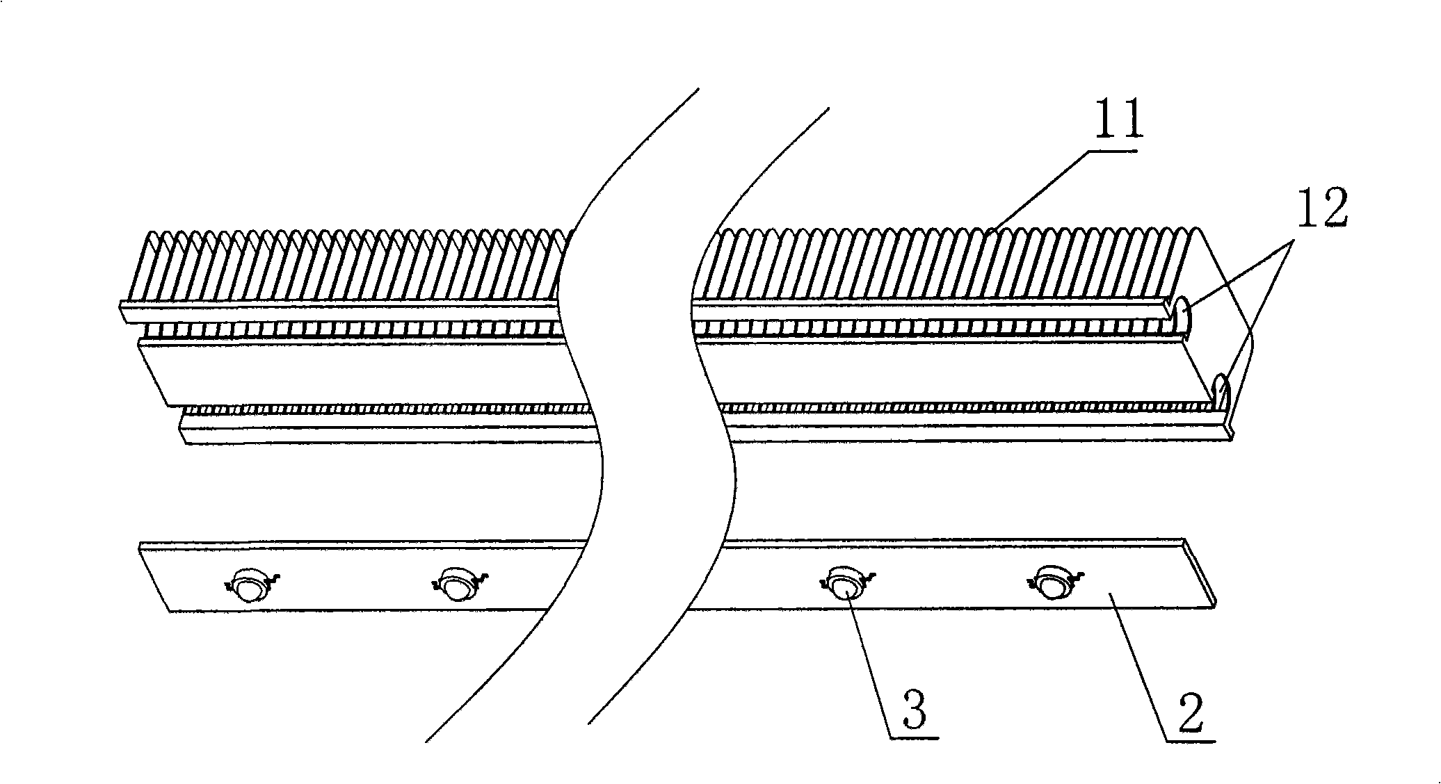
The invention discloses a radiating method of an LED radiator and also discloses the radiator for implementing same, and the radiator comprises a radiating support and a plurality of LED lights. A metal basal plate the width of which is slightly smaller than that of the radiating support is arranged on the front side of the radiating support, and a printed circuit which can be connected with the LED lights is longitudinally arranged in the middle position of the metal basal plate; the LED lights are welded on the printed circuit at intervals, and are fixed on the metal basal plate to form an integral structure. The invention has simple structure, and the metal basal plate and the radiating support are separately arranged to be convenient for manufacture; the printed circuit is arranged onthe metal basal plate, and the LED lights can be directly welded, and can be fixed on the radiating support by radiating silicon grease so as to form an integral radiating structure; the heat of the LED lights can be rapidly radiated, thereby reducing the speed of LED brightness decline and greatly prolonging the service life of the LED lights; the LED lights can be used for more than 50000 hoursat least by practical tests.
Description
Heat dissipation method of LED radiator and radiator implementing the method technical field The invention relates to an LED heat sink, in particular to a heat dissipation method for an LED heat sink and a heat sink implementing the method. Background technique Most of the traditional road lamps use high-power mercury lamps, metal halide lamps or high-pressure sodium lamps as light sources. High, lighting effects are unsatisfactory in terms of color rendering and anti-glare performance. At the same time, the development of semiconductor light-emitting diodes (LEDs) is extremely rapid. In recent years, the luminous efficiency of some LEDs has greatly exceeded that of incandescent lamps, and even exceeded that of fluorescent lamps. Compared with the traditional floodlight electric light source, the LED light source is basically non-toxic, non-electromagnetic pollution, and has many advantages such as small size, low energy consumption, high luminous efficiency, relatively l...
Claims
Login to View More Application Information
Patent Timeline
 Patent Type & AuthorityPatents(China)
IPC IPC(8): F21V29/00H01L23/36F21Y101/02F21V29/76F21V29/89F21Y103/10F21Y115/10
Inventor安波
OwnerDONGGUAN PERFECT SCI & TECH