Color filter substrate and color display device including the same

一种彩色滤波器、基板的技术,应用在仪器、滤光片、静态指示器等方向,能够解决不能分开认出等问题

Inactive Publication Date: 2009-11-11
DAWNCREST IP LLC
View PDF6 Cites 0 Cited by
  • Summary
  • Abstract
  • Description
  • Claims
  • Application Information

AI Technical Summary

Problems solved by technology

In a liquid crystal display device using a color filter of a conventional structure, the maximum distance from the center line Cr of the colored layer of R across the colored layer of G to the center line Cb of the colored layer of B is approximately 150 μm, so the visual acuity of 1.0 When the observer looks at the display screen at a distance of 50 cm, the maximum distance from the center line Cr of the color filter film of R to the center line of the color filter film of B across the color filter film of G is approximately 150 μm. , so the regions of each coloring layer cannot be recognized separately, but the color after additive color mixing will be seen
Therefore, viewing the image without realizing the coloring area of ​​each color constituting the unit pixel

Method used


Image

  • Color filter substrate and color display device including the same
  • Color filter substrate and color display device including the same
  • Color filter substrate and color display device including the same

Examples


Embodiment 1

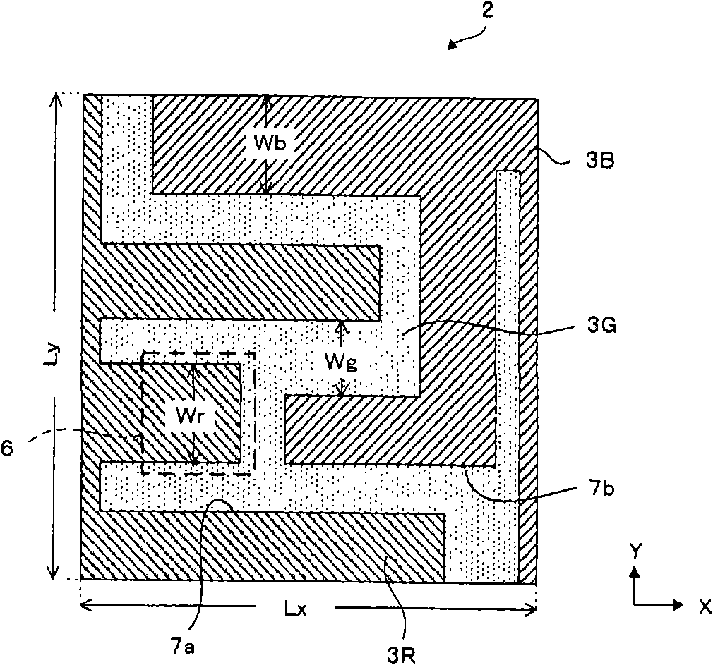
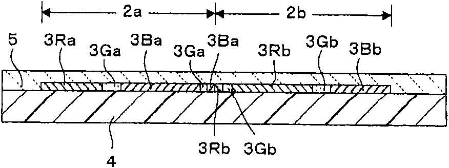
[0044] The color filter substrate 1 of the first embodiment will be described with reference to the drawings. figure 1 It is a schematic plan view of the unit pixel 2 of the color filter substrate 1 .

[0045] Such as figure 1 As shown, the unit pixel 2 has three sub-pixels of a red sub-pixel 3R, a green sub-pixel 3G, and a blue sub-pixel 3B from the left side. The three sub-pixels are separated by a boundary line 7a and a boundary line 7b. Each sub-pixel is composed of planar regions with approximately equal areas. Any sub-pixel consists of contiguous regions. That is, each color sub-pixel is formed by one region. The adjacent red sub-pixel 3R and green sub-pixel 3G have a shape that meshes with each other, and the green sub-pixel 3G and blue sub-pixel 3B also have a shape that meshes with each other. More specifically, the red sub-pixel 3R has three protrusions protruding to the right from the upper side to the lower side. The length of the second protrusion from the...

Embodiment 2

[0052] The color filter substrate 1 of the second embodiment will be described with reference to the drawings. Figure 4 It is a schematic plan view of the unit pixel 2 of the color filter substrate 1 .

[0053] Figure 4 in, with figure 1Similarly, a red sub-pixel 3R, a green sub-pixel 3G, and a blue sub-pixel 3B are formed in the unit pixel 2 . Each sub-pixel has a planar shape that meshes with adjacent sub-pixels, and has an approximately equal area. The maximum line width Wr, Wg, Wb of each sub-pixel is not more than 150 μm. Alternatively, the planar shape of each sub-pixel does not include the square region 6 with a side of 150 μm. In addition, the area of ​​the unit pixel 2 is 0.1mm 2 ~0.6mm 2 . The length of the boundary lines 7 a and 7 b between the sub-pixels is approximately 90% of the peripheral length of the unit pixel. In addition, any sub-pixel is not a periodic shape within a unit pixel.

[0054] In addition, on each sub-pixel, transparent electrodes h...

Embodiment 3

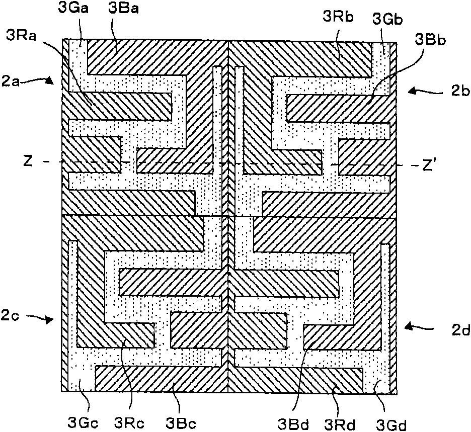
[0062] A schematic plan view of the color filter substrate 1 of the third embodiment is shown in FIG. 7(A) and FIG. 7(B). Both are cases where the unit pixel 2 is composed of sub-pixels of two colors. Use the same symbols for the same parts or parts with the same functions.

[0063] As shown in FIG. 7(A) , a cyan sub-pixel 3C of cyan and a magenta sub-pixel 3M of magenta are configured to mesh with each other. On each sub-pixel, a transparent electrode 8C and a transparent electrode 8M having substantially the same shape as the sub-pixel are formed electrically separated from each other. Each sub-pixel is composed of continuous planar regions with approximately equal areas, and has shapes that mesh with each other. The maximum line width Wc and Wm of each sub-pixel is not more than 150 μm. Alternatively, any sub-pixel has a continuous shape that does not include a square region 6 with a side of 150 μm inside. Also, any sub-pixel is not of periodic shape.

[0064] The cyan...


PUM

PropertyMeasurementUnit
areaaaaaaaaaaa
areaaaaaaaaaaa
areaaaaaaaaaaa

Abstract

The invneiton provides a color filter substrate and color display device including the same. In a color filter substrate (1) in which unit pixels (2), each of which is formed of sub-pixels (3) of a plurality of colors, are arranged two-dimensionally in matrix, when an area of each of the unit pixels (2) exceeds 0.1 mm2, a viewer has not been able to recognize additive color mixture of the sub-pixels (3), and display quality of the color filter substrate (1) has been decreased. In view of this, a configuration is adopted, in which such a plurality of the sub-pixels (3) have areas substantially equal to each other or one another, and each of the sub-pixels (3) has a continuous planar shape in which a line width does not exceed 150 mum, the shape engaging with a sub-pixel (3) adjacent thereto.

Description

technical field [0001] The present invention relates to a color filter substrate having a unit pixel having a relatively large area, and a color display device such as a liquid crystal display device and an EL element using the color filter substrate. Background technique [0002] A liquid crystal display device that performs color display or a color display device using a PDP or an EL element has been put into practical use. In these display devices, for example, sub-pixels of three colors, red (R), green (B), and blue (B), constitute one unit pixel, and perform multicolor display by additive color mixing. In this case, the area of ​​the unit pixel is reduced so that the observer cannot recognize each sub-pixel individually. This allows for additive color mixing. [0003] FIG. 13(A) is a schematic perspective view showing an exploded state of the liquid crystal display device 100 having a color filter, and FIG. 13(B) is an explanatory diagram showing the layout of the col...

Claims


Application Information

Patent Timeline
Patent Type & Authority Applications(China)
IPC IPC(8): G02B5/20G02F1/1335H01L27/02H01L27/32H01L51/50H01J17/49G02F1/133G02F1/1343
CPCG02F2001/134345G09G2300/0452G02F1/133514G02F1/133555G02F1/136286G02F2201/123G02F2201/52G02F2201/122G02F1/134345
Inventor 福地高和
Owner DAWNCREST IP LLC
Why Eureka
Try Eureka