Display driver and electro-optical device

A display driver and electro-optic technology, applied in identification devices, static indicators, cathode ray tube indicators, etc., can solve the problems of large power consumption and increased terminal power consumption, and achieve simplified structure, reduced quantity, and miniaturization Effect

Inactive Publication Date: 2008-12-17
SEIKO EPSON CORP
View PDF3 Cites 0 Cited by
  • Summary
  • Abstract
  • Description
  • Claims
  • Application Information

AI Technical Summary

Problems solved by technology

Another reason is that an increase in the number of terminals leads to an increase in power consumption due to the large power consumption of the input buffer or the I / O buffer connected to the terminal

Method used


Image

  • Display driver and electro-optical device
  • Display driver and electro-optical device
  • Display driver and electro-optical device

Examples


Embodiment Construction

[0040] Embodiments of the present invention will be described in detail below with reference to the accompanying drawings. The embodiments described below are not intended to limit the content of the invention as claimed. In addition, not all the configurations described below are essential configuration requirements of the present invention.

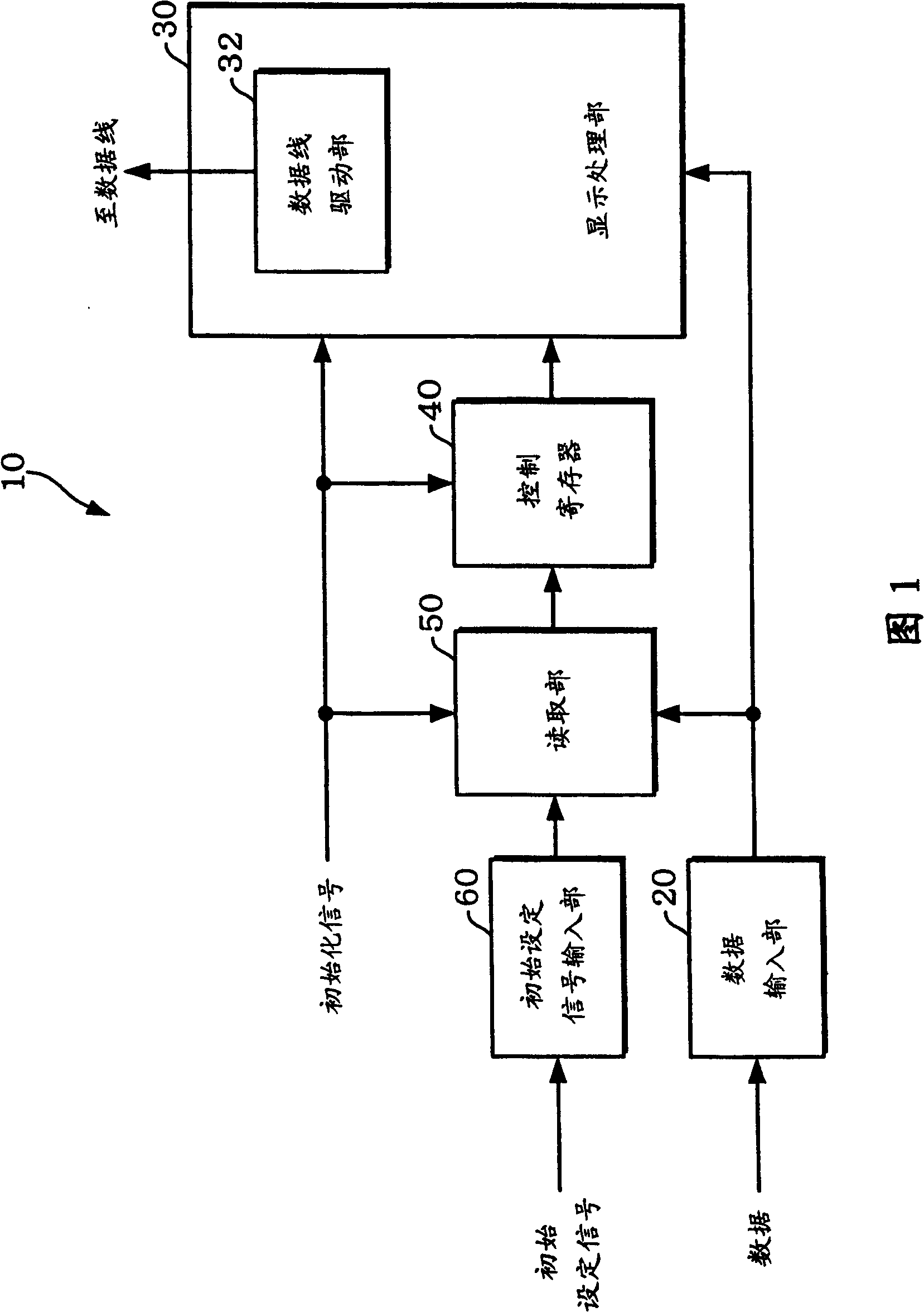
[0041] FIG. 1 shows a block diagram of a display driver according to one embodiment of the present invention. The display driver 10 of this embodiment includes a data input unit 20 , a display processing unit 30 , a control register 40 , and a reading unit 50 .

[0042]Display data or setting data (data in a broad sense) is input to the data input unit 20 . Display data or setting data is provided by a display controller (not shown). Such a function of the data input unit 20 is realized by, for example, one or more data input terminals (terminals in a broad sense). Alternatively, the function of the data input unit 20 is realized by...


PUM


Abstract

The invention provides a display driver (10) for driving a plurality of data lines of an electro-optical panel, which comprises: a data input part (20), into which display data or setting data (32) is input; a display processing part (30), having a data line driving part, driving a plurality of data lines according to the display data input by the data input part (20); the control register (40), used to control the display processing part (30); the reading part (50) , which reads the setting data input through the data input part (20) based on the initial setting signal; wherein, at least one of the display processing part (30) and the control register (40) is set to initial by the initializing signal After the state, the setting data read by the reading unit (50) is set in the control register (40). The display processing unit (30) is controlled based on the setting data set in the register (40).

Description

technical field [0001] The invention relates to a display driver and an electro-optical device. Background technique [0002] An electro-optical device represented by a liquid crystal display device includes a plurality of scanning lines, a plurality of data lines and a plurality of pixels. A plurality of scan lines are sequentially selected by a scan driver within one vertical scan period. During each horizontal scan, a plurality of data lines are driven by the data driver. [0003] For example, in a pixel unit, a display controller serially supplies display data to a data driver. The data driver shifts serially input display data and generates display data for each horizontal scan. And, the data driver drives the data lines based on one horizontally scanned display data. For example, in the data driver, depending on the mounting state, the direction of shifting of the display data supplied from the display controller can be changed. Therefore, the wiring between the d...

Claims


Application Information

Patent Timeline
Patent Type & Authority Patents(China)
IPC IPC(8): G09G3/20G09G3/36G02F1/133G09F9/30G09G5/00H01L27/00
CPCG09G3/3614G09G3/3688G09G3/3696G09G2310/027G09G2310/0283
Inventor 森田晶
Owner SEIKO EPSON CORP
Why Eureka
Try Eureka