Electric field driving device and electronic apparatus

A driving type, electric field technology, applied in instruments, nonlinear optics, optics, etc., can solve problems such as display quality deviation, liquid crystal alignment state disorder, and display quality degradation

Active Publication Date: 2013-11-06
138 EAST LCD ADVANCEMENTS LTD
View PDF1 Cites 0 Cited by
  • Summary
  • Abstract
  • Description
  • Claims
  • Application Information

AI Technical Summary

Problems solved by technology

The electric field is disturbed near the end of such a slit, and as a result, there is a problem that the alignment state of the liquid crystal is disturbed, domains are generated, etc., which leads to a decrease in display quality.
In addition, if the number of ends of the slits is different among a plurality of sub-pixels corresponding to the same color, there is a problem that the direction of disturbance of the electric field is different for each sub-pixel, resulting in variation in display quality.

Method used


Image

  • Electric field driving device and electronic apparatus
  • Electric field driving device and electronic apparatus
  • Electric field driving device and electronic apparatus

Examples


no. 1 approach

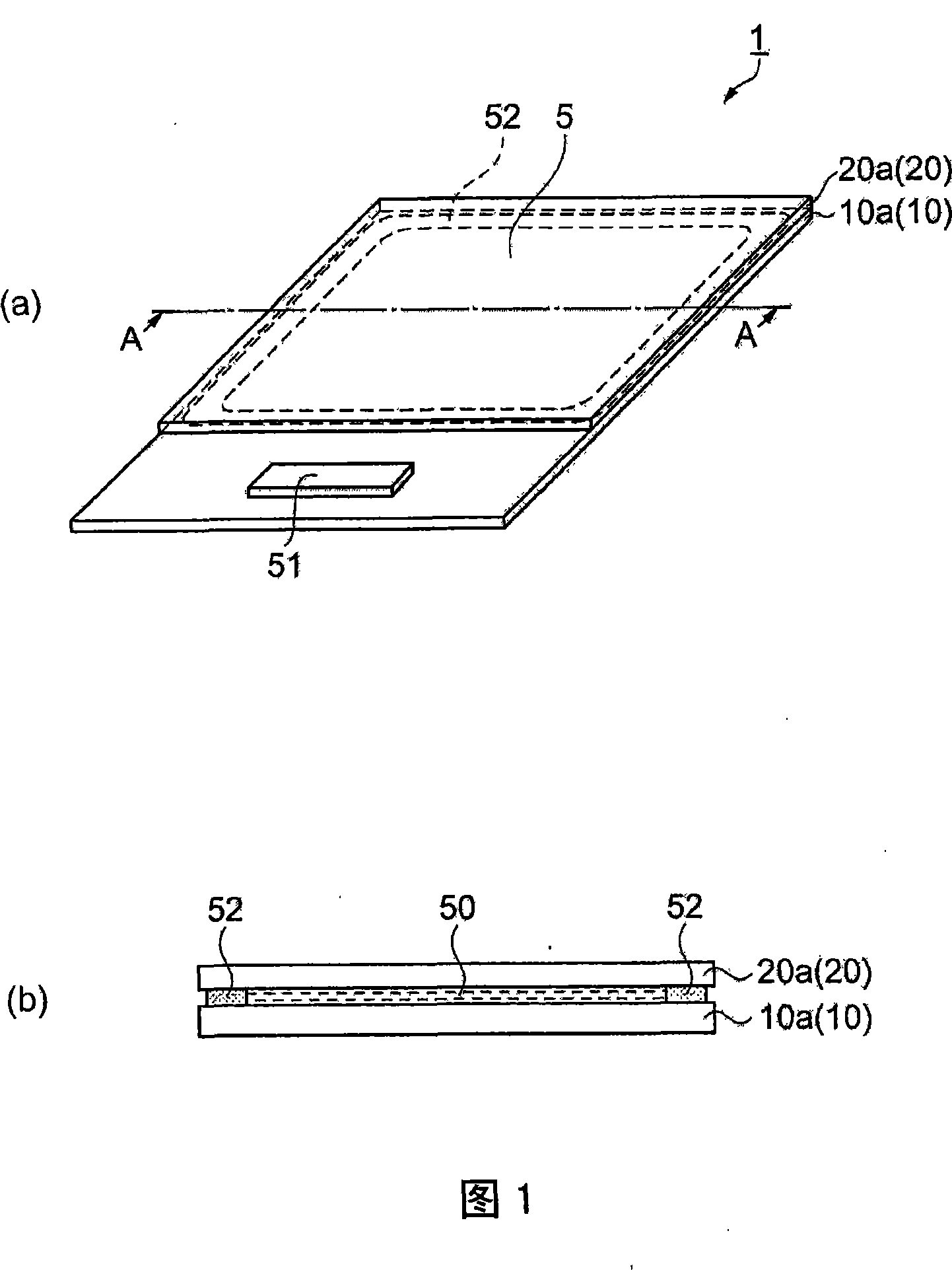
[0069] figure 1 It is a schematic diagram of the liquid crystal device 1 as an electric field drive type device, (a) is a perspective view, and (b) is a cross-sectional view taken along line A-A in (a). The liquid crystal device 1 has an element substrate 10 a and a counter substrate 20 a that are laminated to face each other via a frame-shaped sealing material 52 . The element substrate 10 a includes a glass substrate 10 as one substrate, and the counter substrate 20 a includes a glass substrate 20 . A liquid crystal 50 is sealed in a space surrounded by the element substrate 10 a , the counter substrate 20 a , and the sealing material 52 . The element substrate 10a is larger than the opposing substrate 20a, and a part thereof is attached in a state protruding from the opposing substrate 20a. On this protruding portion, a drive IC 51 for driving the liquid crystal 50 is mounted. The liquid crystal 50 corresponds to "a substance driven by an electric field generated by a po...

no. 2 approach

[0092] Next, a second embodiment will be described. The liquid crystal device 1 of this embodiment is based on the first embodiment, except that the arrangement of the common electrodes 26 and the slits 27 and the configuration of the pixels 3 are changed, and other points are the same as those of the first embodiment. In each of the drawings used in the following description, the same reference numerals are attached to the same elements as those of the first embodiment, and description thereof will be omitted.

[0093] Figure 8 It is a plan view extracting and showing a portion corresponding to two adjacent pixels 3 in the pixel region 5 of the liquid crystal device 1 of the present embodiment. The pixels 3 of the present embodiment are composed of four colors arranged along the longitudinal direction of the slit 27. 4 sub-pixels. Specifically, the pixel 3 is composed of sub-pixels 4R, 4G, 4B, and 4C that contribute to the display of red, green, blue, and cyan. Therefore,...

no. 3 approach

[0100] Next, a third embodiment will be described. This embodiment is also based on the first embodiment, and the arrangement of the common electrode 26 and the slit 27 and the configuration of the pixel 3 are changed, and other aspects are the same as the first embodiment.

[0101] Figure 9 It is a plan view extracting and showing a part of the pixel region 5 of the liquid crystal device 1 of the present embodiment. The pixel 3 in this figure is composed of two-color sub-pixels 4 arranged along the longitudinal direction of the slit 27 . Specifically, the pixel 3 is composed of sub-pixels 4R and 4G that contribute to red and green display.

[0102] In the present embodiment, a set of two pixels 3 arranged along the longitudinal direction of the slit 27 is called "pixel block 2". The layout of the pixel region 5 including the pattern of the common electrode 26 and the slit 27 is composed of the pixel block 2 as the minimum unit of repetition.

[0103] Nine strip-shaped po...


PUM


Abstract

The invention provides an electric field driving device and an electronic apparatus that can reduce slit end amount, and restrain domain generation. As one of the field driving device, a liquid crystal device has more than two rectangle sub-pixel (4) corresponding to various color in pixel region. The liquid crystal device has: a pair of substrates opposite configured, a liquid crystal configured on the substrate, a pixel electrode formed according with each sub-pixel (4) on a surface opposite to the liquid crystal of one substrate. The common electrode (26) has a plurality of slits (27) that at least partly overlap the pixel electrodes in plan view. At least a portion of the slits (27) are respectively provided continuously over a plurality of the sub-pixels (4). Each of the sub-pixels (4) corresponding to the same color includes the same numbers of end portions (28) of the plurality of slits (27).

Description

technical field [0001] The invention relates to an electric field driven device and electronic equipment. Background technique [0002] One of the electric field driven type devices is a liquid crystal device that modulates transmitted light by driving the liquid crystal with an electric field. As one form of such a liquid crystal device, there is known a liquid crystal device in FFS (Fringe Field Switching) mode in which liquid crystal is driven by a transverse electric field parallel to the substrate (see Patent Document 1). This liquid crystal device has a pixel electrode and a common electrode laminated on the pixel electrode on a surface facing the liquid crystal on one substrate, wherein a plurality of slits are provided on the common electrode. In this configuration, when a driving voltage is applied between the pixel electrode and the common electrode, an electric field having electric force lines extending from the upper surface of the common electrode through the ...

Claims


Application Information

Patent Timeline
Patent Type & Authority Patents(China)
IPC IPC(8): G02F1/1343G02F1/139G02F1/1362
CPCG02F1/1362G02F2201/121G02F2201/123G02F1/134372
Inventor 若林淳一
Owner 138 EAST LCD ADVANCEMENTS LTD
Why Eureka
Try Eureka