
Digital plate and method for obtaining position of digital plate

A digital tablet and logical position technology, which is applied in the field of digital tablet and digital tablet position acquisition, can solve the problems of long position acquisition time, general products and methods do not have suitable structures and methods, inconvenience, etc., and reduces the number of switches , the effect of easy expansion of the number of antennas

Active Publication Date: 2009-11-11
SUNREX TECH
View PDF0 Cites 1 Cited by
  • Summary
  • Abstract
  • Description
  • Claims
  • Application Information

AI Technical Summary

Problems solved by technology

However, when judging the position of the digital pen in the aforementioned case, the original output signals output by these antennas must be digitized and compared in size to determine the coordinates of the digital pen, which has the disadvantage of taking a long time to acquire the position.
[0004] It can be seen that the above-mentioned existing digital board and the position obtaining method of the digital board thereof obviously still have inconvenience and defects in product structure, position obtaining method and use, and need to be further improved urgently.
In order to solve the above-mentioned problems, the relevant manufacturers have tried their best to find a solution, but no suitable design has been developed for a long time, and there is no suitable structure and method for general products and methods to solve the above-mentioned problems. This is obviously a problem that relevant industry players are eager to solve

Method used


Image

  • Digital plate and method for obtaining position of digital plate
  • Digital plate and method for obtaining position of digital plate
  • Digital plate and method for obtaining position of digital plate

Examples


Embodiment Construction

[0035] In order to further elaborate the technical means and effects that the present invention takes to achieve the intended invention purpose, below in conjunction with the accompanying drawings and preferred embodiments, the specific implementation methods, Structure, method, step, feature and effect thereof are as follows in detail.

[0036] The aforementioned and other technical contents, features and effects of the present invention will be clearly presented in the following detailed description of preferred embodiments with reference to the drawings. Through the description of the specific implementation mode, when the technical means and functions adopted by the present invention to achieve the predetermined purpose can be obtained a deeper and more specific understanding, but the accompanying drawings are only for reference and description, and are not used to explain the present invention be restricted. Before the present invention is described in detail, it should ...


PUM


Abstract

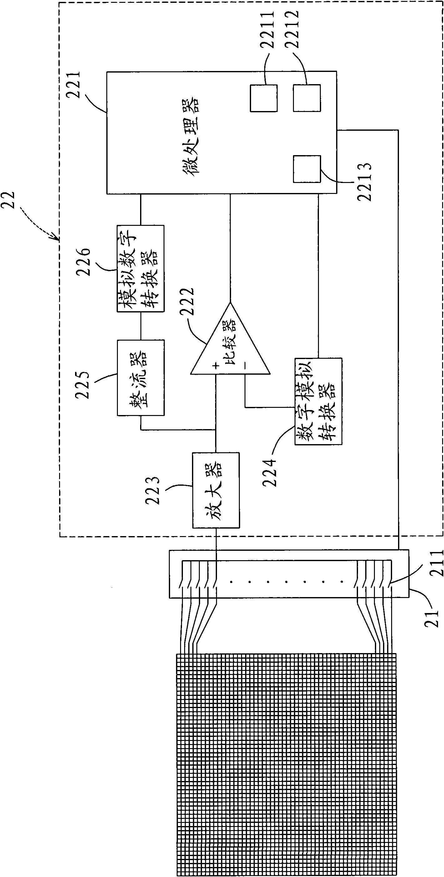
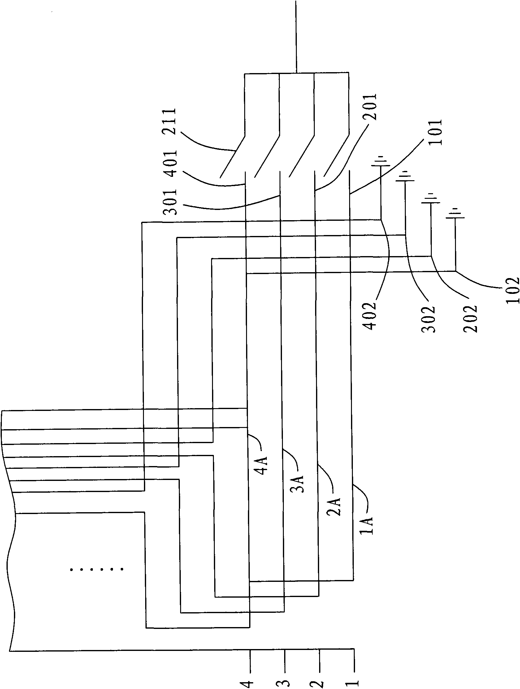
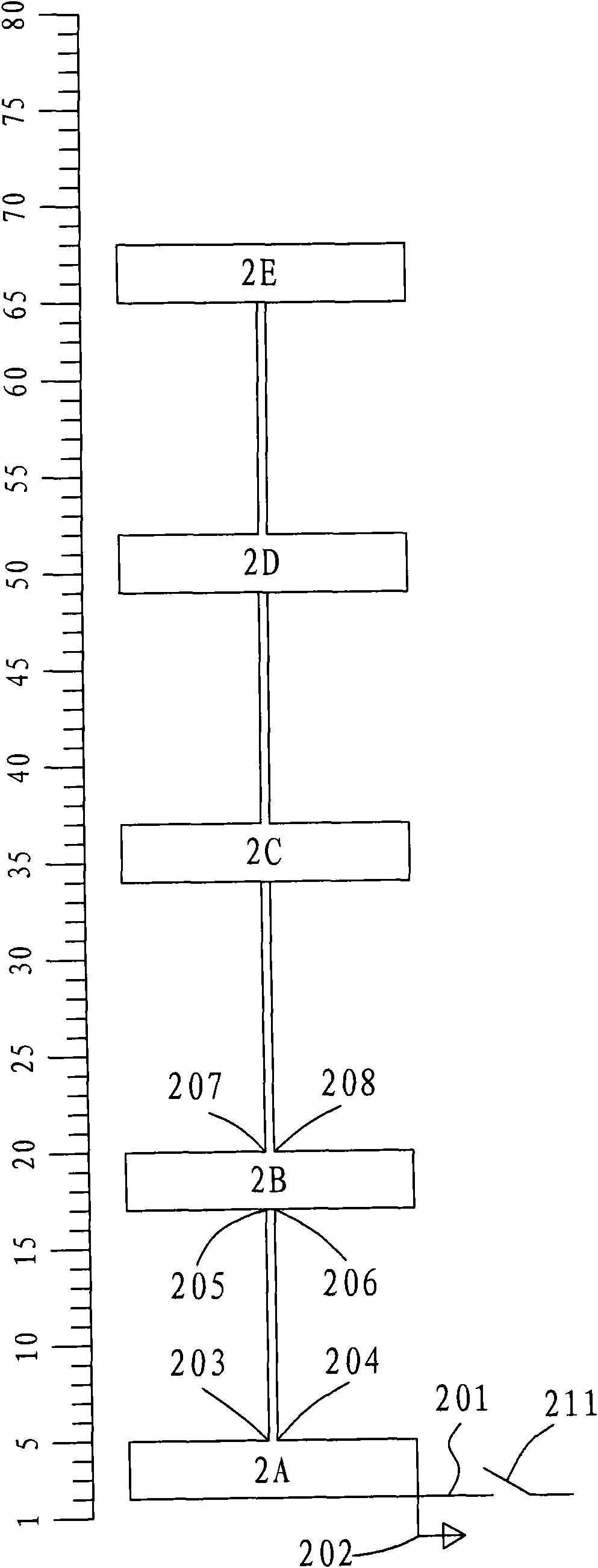
The invention relates to a digital plate and a method for obtaining the position of the digital plate. The digital plate comprises a plurality of antenna loops, a plurality of switches and a control circuit, wherein the switches are electrically connected with corresponding antenna loops; each antenna loop is provided with a basic antenna and at least one extended antenna connected with the basic antenna in series; the sequence number combination of the antenna loop to which any three adjacent antennae of the basic antennae and the extended antennae belong is unique; the control circuit is provided with a logical position table for recording the sequence number combination and a corresponding logical position; and the control circuit sequentially controls the switches to be switched on to receive an original output signal of each group of antenna loops, and then, the position of a digital pen can be judged according to the logical position table. The invention can achieve the efficacies of the reduction of the amount of switches the easy extension the antenna. In the invention, a microprocessor is also used for adjusting a quasi-phase value in time, and thus, the position of the digital pen on the digital plate can be quickly obtained only by a comparison and look-up method for the simple original output signal and the quasi-phase value.

Description

technical field [0001] The present invention relates to a digital board and a method for obtaining the position of the digital board, in particular to a method for obtaining the coordinate position of the digital pen quickly by combining any three adjacent antennas into a unique combination and matching the look-up table, which can reduce the number of switches , and the number of antennas is expanded to facilitate the function of the digital board and the method for obtaining the position of the digital board. Background technique [0002] The technology of the digital board has long been known, and its main use is as a drawing or handwriting input auxiliary device for a computer, such as a tablet computer. After calculation, it is sent to the computer to generate the corresponding position. In the current design, the working area of ​​the digital board is composed of two sets of vertical and horizontal interlaced antennas. An antenna must be equipped with a switch to dete...

Claims


Application Information

Patent Timeline
Patent Type & Authority Applications(China)
IPC IPC(8): G06F3/041H01Q21/28
Inventor 蔡火炉
Owner SUNREX TECH
Learn More