
Electronic current transformer signal reduction method based on Rogowski coil

A current transformer and electronic technology, which is applied in the direction of inductors, circuits, transformers, etc., can solve the problems of non-convergence in the integration process, improve the steady-state index and transient index, avoid angle deviation, and improve the integration accuracy. Effect

Active Publication Date: 2012-09-26
GUODIAN NANJING AUTOMATION
View PDF0 Cites 0 Cited by
  • Summary
  • Abstract
  • Description
  • Claims
  • Application Information

AI Technical Summary

Problems solved by technology

The software integration method of the existing analog hardware solution will also output a large DC component due to continuous digital integration, and even the integration process will not converge

Method used


Image

  • Electronic current transformer signal reduction method based on Rogowski coil
  • Electronic current transformer signal reduction method based on Rogowski coil
  • Electronic current transformer signal reduction method based on Rogowski coil

Examples


Embodiment Construction

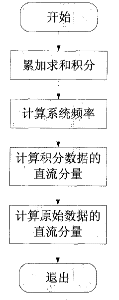
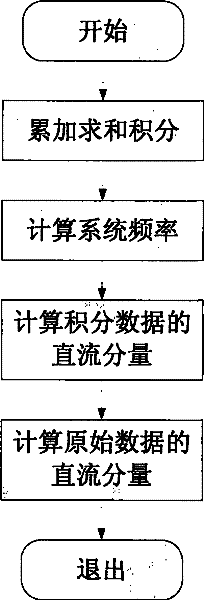
[0021] The present invention provides a kind of electronic current transformer signal restoration method based on Rogowski coil, it is characterized in that: comprise the following steps:

[0022] 1) Use the formula (1) to digitally integrate the secondary side signal of the electronic current transformer to obtain the integral output value:

[0023] y(i)=y(i-1)+x(i)-z 2 -α*z 1 Formula 1)

[0024] In the formula, z 1 ,z 2 The initial value of is set to 0. α depends on the actual situation of the voltage level or capacity of the power system. It is generally set to a decay period of 0.5 seconds to 2 seconds. Assuming it is t (unit is second), the decay coefficient is:

[0025] α=1 / (t*f s ) formula (2)

[0026] 2) Using the zero-crossing algorithm, the system frequency f is calculated according to the integrated data y. Assume that the first positive zero-crossing point occurs at the time of M and M+1, that is, y(M)0, and the next positive zero-crossing point occurs ...


PUM


Abstract

The invention discloses an electronic current transformer signal reduction method based on a Rogowski coil, which is characterized in that: the method comprises the following steps: 1) performing digital integration on signals on the secondary side of an electronic current transformer to obtain an integral output value; 2) calculating a system frequency f according to data y after integration by a zero crossing algorithm; 3) calculating a direct current component z1 of data y(i) after the integration according to the calculated system frequency f by a summation algorithm; 4) obtaining a direct current component z2 of data x(i) before the integration according to the change rate of the direct current component z1 before the integration; and 5) filtering a direct current component z2 in an integration algorithm, and filtering the direct current z1 after the integration by a point-wise attenuation method in the process of digital integration to obtain a final integral output value. The electronic current transformer signal reduction method can filter the direct current components before and after the integration so as to improve the integral accuracy, avoid the angular deviation problem in a lossy integration algorithm, and improve the steady state and transient state indexes of devices.

Description

technical field [0001] The invention relates to a method for restoring a current differential signal output by a Rogowski coil in an electronic transformer system, and belongs to the technical field of power systems. Background technique [0002] With the expansion of the grid scale, the inherent CT saturation and ferromagnetic resonance of traditional electromagnetic transformers in the region are becoming more and more serious, and new transformers are needed to solve these problems. At the same time, with the development of semiconductor technology, computer technology, and communication technology, the research and application of active electronic transformers have made great progress, and China's power system is already in the transition stage from pilot application to full promotion. In the active electronic current transformer system, the Rogowski coil is used as the current sensing device, which has the characteristics of no magnetic saturation, good transient charac...

Claims


Application Information

Patent Timeline
Patent Type & Authority Patents(China)
IPC IPC(8): H01F38/28G06F17/10
Inventor 郭乐李广华安同平
Owner GUODIAN NANJING AUTOMATION
Learn More