
Chip packaging structure

A chip packaging structure and chip technology, applied in electrical components, electrical solid devices, circuits, etc., can solve the problem of inability to increase the number of conductive balls to increase the number of pins

Inactive Publication Date: 2011-05-04
CHIPMOS TECH INC
View PDF3 Cites 0 Cited by
  • Summary
  • Abstract
  • Description
  • Claims
  • Application Information

AI Technical Summary

Problems solved by technology

[0006] To sum up, the current stacked packaging technology used for ball grid array packaging cannot meet the needs of effectively increasing the number of conductive balls to increase the number of pins

Method used


Image

  • Chip packaging structure
  • Chip packaging structure
  • Chip packaging structure

Examples


Embodiment Construction

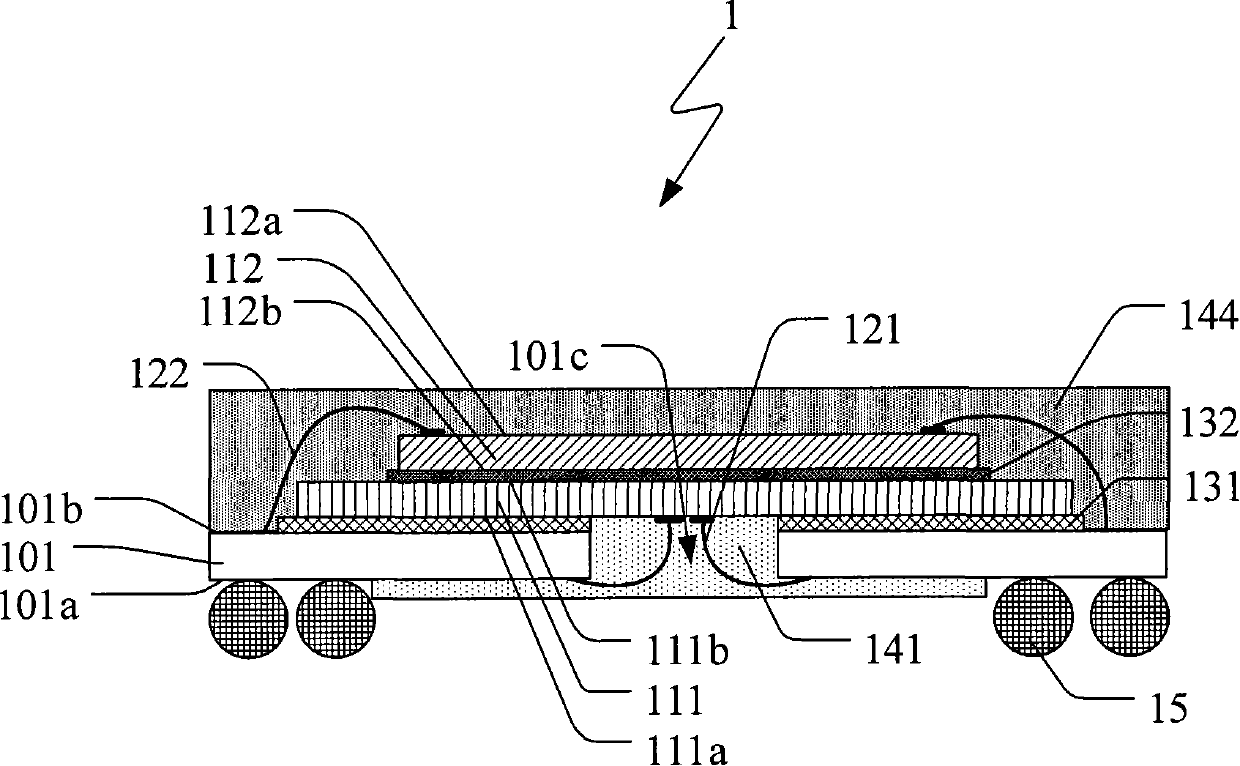
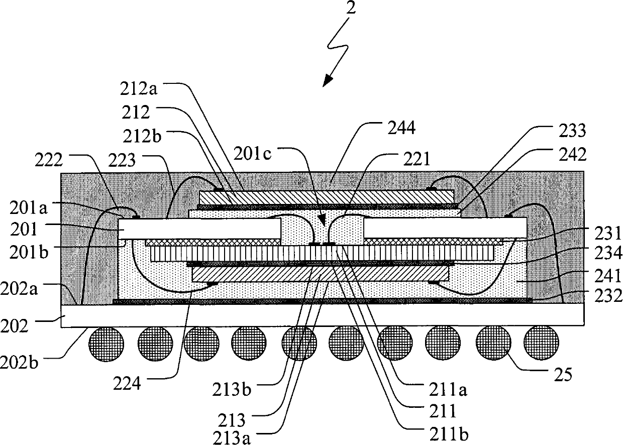
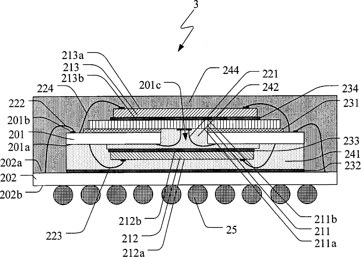
[0016] The basic concept of the chip packaging structure of the present invention is to use two substrates to perform multi-chip stack packaging (Package on Package, PoP), so that at least one of the two substrates does not need to open through holes for electrically connecting chips , and the suit can maintain a complete surface. Therefore, the conductive balls can be covered on the above-mentioned complete surface without avoiding the above-mentioned through holes, and the ball grid array (BGA) package can be carried out, and the number of ball grids can be greatly increased to cope with the increase in a certain area. Trends in chip package structure pin counts.

[0017] Such as figure 2 As shown in the part, the chip packaging structure 2 of the present invention as a whole includes at least a first substrate 201, a second substrate 202, a plurality of chips, a first wire part 221, a second wire part 222, a third wire part 223, a first wire part 223, a The four wire par...


PUM


Abstract

The invention relates to a chip packaging structure which comprises a first substrate, a second substrate and a plurality of chips, wherein one of the chips is jointed on the first substrate and is electrically connected with the first substrate through a through hole of the first substrate. Thus, the second substrate has no need of being provided with a through hole for electrically connecting the chip to be beneficial to maintaining a complete surface on which conducting spheres are distributed.

Description

technical field [0001] The present invention relates to a chip package structure; in particular, a chip package structure using stack package (Package ON Package, POP) technology. Background technique [0002] Under the trend of miniaturization of various electronic products, the internal space of various electronic products is decreasing. Therefore, various manufacturers are all committed to reducing the size of the internal components of electronic products. How to install more chips in a smaller space has become an important issue in increasing the integration of electronic products. Stacked packaging (Package on Package, PoP) technology is to stack multiple chips in a chip packaging structure, so as to package and arrange multiple chips in the same area. With the help of this stacked packaging technology, the chip packaging structure can significantly reduce the area occupied by multiple chips by only slightly increasing the thickness. Therefore, the package-on-packag...

Claims


Application Information

Patent Timeline
Patent Type & Authority Patents(China)
IPC IPC(8): H01L25/00H01L25/065H01L23/488
CPCH01L25/03H01L24/73H01L2224/16145H01L2224/32225H01L2224/48227H01L2224/4824H01L2224/73215H01L2224/73265H01L2924/15311H01L2924/181H01L2924/19107
Inventor 吴政庭卢一成张育诚王姿婷
Owner CHIPMOS TECH INC
Learn More