Pipe cutting and moving all-in-one device
A technology of equipment and pipes, which is applied in the field of pipe cutting and moving integrated equipment, can solve the problems of large space occupied by equipment and wear of the outer surface of pipes, and achieve the effect of maintaining pipe quality and surface integrity
- Summary
- Abstract
- Description
- Claims
- Application Information
AI Technical Summary
Problems solved by technology
Method used
Image
Examples
Embodiment 1
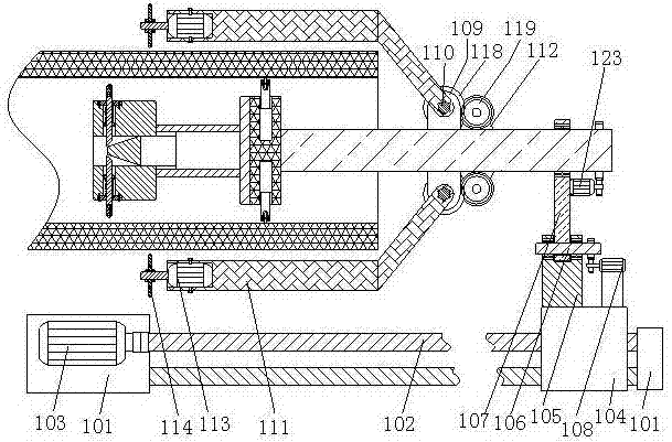
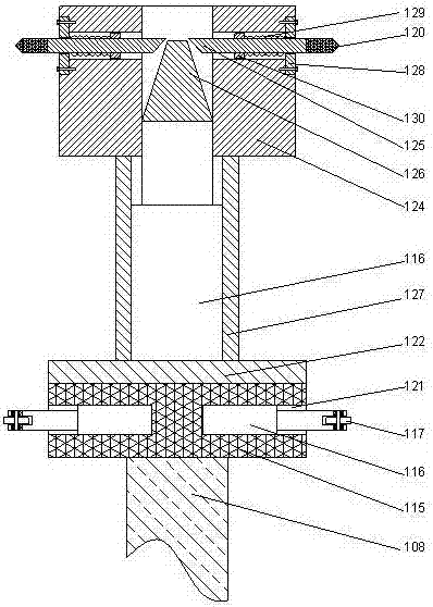
[0025] Such as figure 1 , 2 As shown, an integrated equipment for cutting and moving pipes, including a horizontal driving device, a knife moving device, a cutting device and a positioning and moving device;
[0026] The horizontal moving device includes a screw support 101 and a screw 102 arranged above the screw support, and a screw drive motor connected to the screw is provided on one side of the screw support. 103, a moving support 104 is arranged on the screw rod;
[0027] The tool moving device includes a connecting rod support 105 arranged on the moving support, the connecting rod support is perpendicular to the upper end surface of the moving support, and on the connecting rod support A rotating shaft 106 is provided, and the rotating shaft is rotatably connected to the connecting rod support through a bearing, and a connecting rod 107 is arranged on the rotating shaft; The connecting rod driving motor 108 that the rotating shaft rotates; a support rod 108 is provid...
Embodiment 2
[0035]This embodiment is based on Embodiment 1, in order to prevent the inner wall of the pipe from being worn by the hydraulic cylinder during the cutting process, in this embodiment, preferably, a roller 117 is provided on the telescopic rod of the hydraulic cylinder. Make the inner wall of the pipe relative to the telescopic rod of the hydraulic cylinder to form relative rolling friction, so as to avoid the inner wall of the pipe being worn and affecting the quality of the pipe.
[0036] In this embodiment, a preferred structure for driving the central shaft is disclosed. Preferably, a gear 118 is provided on the central shaft, and a driving gear meshing with the gear is provided on the positioning rod driving motor. 119.
[0037] The positioning rod driving motor drives the driving gear to rotate, so that the driving gear drives the gear on the central shaft to rotate, so that the central shaft rotates. In this embodiment, other structural forms can also be used, such as u...
Embodiment 3
[0040] In this embodiment, on the basis of Embodiment 2, in order to facilitate the installation of the hydraulic cylinder and make its structure more stable, in this embodiment, preferably, a Groove 121, the hydraulic cylinder is clamped inside the groove. By adopting the groove structure, the hydraulic cylinder is clamped on the inner side of the groove, which can be easily fixed and relatively more stable.
[0041] In this embodiment, in order to protect the hydraulic cylinder from being damaged, preferably, an end cover 122 is provided outside the groove, and the end cover is detachably connected to the positioning disc. The end cover is used to make the hydraulic cylinder completely inside the positioning disc.
PUM
 Abstract
Description
Claims
Application Information
 - R&D
- Intellectual Property
- Life Sciences
- Materials
- Tech Scout
- Unparalleled Data Quality
- Higher Quality Content
- 60% Fewer Hallucinations
Browse by: Latest US Patents, China's latest patents, Technical Efficacy Thesaurus, Application Domain, Technology Topic, Popular Technical Reports.
© 2025 PatSnap. All rights reserved.Legal|Privacy policy|Modern Slavery Act Transparency Statement|Sitemap|About US| Contact US: help@patsnap.com


