
Optical modulation device, optical modulation method and dispersion pre-compensation transmitter

An optical modulation device and pre-compensation technology, applied in the field of communication transmission, can solve problems such as difficulty in driver implementation, and achieve the effects of easy power adjustment, high gain, and accurate adjustment

Inactive Publication Date: 2009-11-11
HUAWEI TECH CO LTD
View PDF3 Cites 15 Cited by
  • Summary
  • Abstract
  • Description
  • Claims
  • Application Information

AI Technical Summary

Problems solved by technology

Since the gain-bandwidth product of electrical devices is constant, the driver must have high gain when the transmission distance is relatively long. At this time, it is a big difficulty to realize broadband at the same time. very difficult

Method used


Image

  • Optical modulation device, optical modulation method and dispersion pre-compensation transmitter
  • Optical modulation device, optical modulation method and dispersion pre-compensation transmitter
  • Optical modulation device, optical modulation method and dispersion pre-compensation transmitter

Examples


Embodiment Construction

[0042] The technical solution of the present invention will be described below in conjunction with specific embodiments.

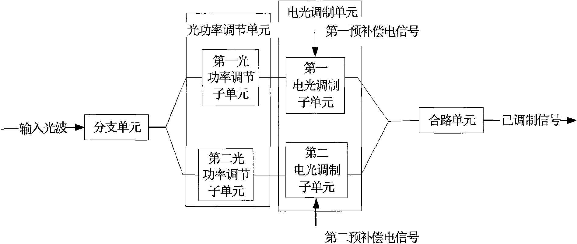
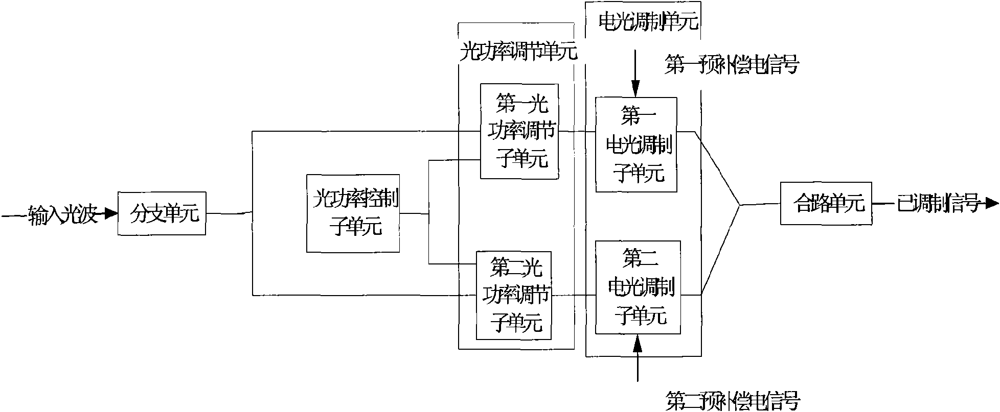
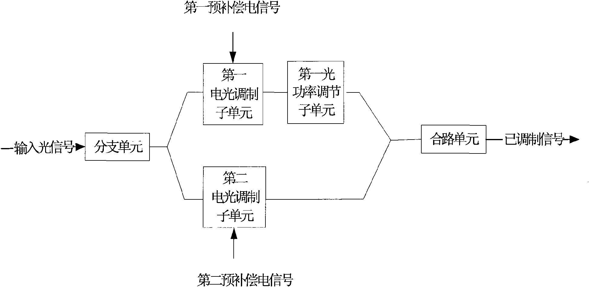
[0043] figure 1 This is a block diagram of the implementation of the optical modulation device provided in the first embodiment of the present invention. The electro-optical modulator is composed of a branch unit, an optical power adjustment unit, an electro-optical modulation unit, and a combining unit.

[0044] The branching unit divides the input optical signal into a first branch optical signal and a second branch optical signal.

[0045] The optical power adjusting unit adjusts the power of at least one optical signal of the first branch optical signal and the second branch optical signal output by the branch unit before outputting.

[0046] The optical power adjustment unit may include one or more of an optical tunable attenuation module, an optical polarization module, and an optical amplification module. The optical tunable attenuation module may be ...


PUM


Abstract

The embodiment of the invention discloses an optical modulation device, an optical modulation method and a dispersion pre-compensation transmitter. The optical modulation device comprises a branching unit, an optical power regulating unit, an electro-optical modulation unit and a combining unit, wherein the branching unit is used for dividing an input optical signal into a first branch optical signal and a second branch optical signal and outputting the first branch optical signal and the second branch optical signal; the optical power regulating unit is used for regulating the power of at least one of the first branch optical signal and the second branch optical signal output by the branching unit and then outputting the first branch optical signal and the second branch optical signal; the electro-optical modulation unit is used for receiving an input pre-compensation electrical signal and modulating the first branch optical signal and the second branch optical signal output by the optical power regulating unit according to the pre-compensation electrical signal so as to generate a first modulation signal and a second modulation signal; and the combining unit is used for combining the first modulation signal and the second modulation signal into a path of modulated signal. Under the condition of high speed, the embodiment of the invention does not need a driver with great difficulty of realization, and meanwhile, power regulation is easier to realize so as to more accurately regulate the power of the output modulated signal.

Description

Technical field [0001] The invention relates to the field of communication transmission, in particular to an optical modulation device, a method and a dispersion pre-compensation transmitter. Background technique [0002] The signal transmission in the optical fiber needs to experience the influence of dispersion. Dispersion is a phenomenon in which the different frequency components of the signal transmitted in the optical fiber or the transmission speed of various mode components of the signal cause signal waveform distortion. The effect of chromatic dispersion on optical transmission is to cause inter-code interference between data pulses. The damage to system performance caused by chromatic dispersion cannot be ignored. Generally, optical fiber transmission systems with a transmission rate of more than 10 Gbit / s require dispersion compensation technology to ensure the transmission function of the system. [0003] In recent years, electrical domain dispersion compensation has ...

Claims


Application Information

Patent Timeline
IPC IPC(8): H04B10/18H04B10/12H04B10/50
CPCH04B2210/254H04B10/5053
Inventor 陶智慧
Owner HUAWEI TECH CO LTD
Learn More