Load ring mounting of pumping plunger

A grommet and plunger technology, which is applied to the components of pumping devices for elastic fluids, fuel injection devices, charging systems, etc. question

Active Publication Date: 2009-11-11
斯塔纳迪恩公司
View PDF0 Cites 2 Cited by
  • Summary
  • Abstract
  • Description
  • Claims
  • Application Information

AI Technical Summary

Problems solved by technology

[0003] Although it is possible to manufacture the sleeve and plunger with this precision, the assembly of the two in the pump housing will still result in a slight misalignment of th

Method used


Image

  • Load ring mounting of pumping plunger
  • Load ring mounting of pumping plunger
  • Load ring mounting of pumping plunger

Examples


Embodiment Construction

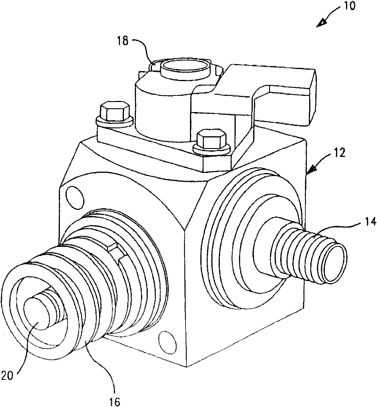
[0016] figure 1 A single plunger fuel pump 10 is shown having a generally cuboidal housing or body 12 with a fuel feed fitting 14 protruding from the right, a single plunger drive assembly 16 protruding from the left, and a Protruding feed control valve 18.

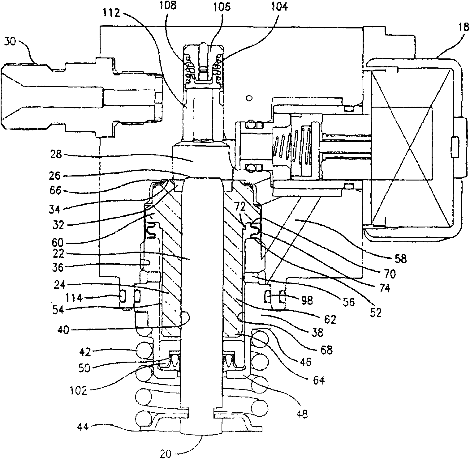
[0017] now refer to figure 1 and figure 2 , it will be readily understood that the engine drive shaft is provided with lug-type cams (not shown) which cause the distal end 20 of the pumping plunger 22 to internally charge the pumping sleeve 24 fixed to the housing ( Feeding) and unloading (discharging) stage reciprocating motion. The other pumping end 26 of the plunger is located in a pump chamber 28, which is filled with fuel at a feed pressure of about 4 bar during the charging phase, and is preferably subject to initial overflow control, pressurizing the fuel in the pump chamber to Approximately 200 bar to be delivered via discharge connection 30 to eg a common rail (not shown). Fuel is supplied directly to the p...


PUM


Abstract

A clamping and seal loading technique for securing the plunger sleeve to the pump housing of a single plunger fuel pump. This is achieved by providing a load ring between a sleeve retainer and the sleeve, such that the axial force applied by the retainer during installation and attachment to the plunger bore wall of the housing, is distributed more evenly on the sleeve and the sealing surface of the sleeve against the housing adjacent to the pumping chamber. The even distribution of force minimizes misalignment of the sleeve and thus maintains concentricity between the sleeve and the plunger.

Description

technical field [0001] The present disclosure relates generally to fuel pumps, and more particularly to a new and improved single plunger fuel pump. Background technique [0002] In a typical high pressure reciprocating plunger fuel feed pump, the plunger reciprocates within a shrouded sleeve that is secured in the bore of the plunger. The sleeve is supported on a shoulder or other mounting surface in the pump housing. For ideal performance and long service life, the outer diameter of the plunger and inner diameter of the sleeve must be precisely sized to close tolerances and installed in such a way that a precise fit is maintained. [0003] While it is possible to manufacture the sleeve and plunger with this precision, the assembly of the two in the pump housing will still result in slight misalignment of the plunger within the sleeve. This misalignment can result in excessive or uneven wear of the plunger, and can also affect the fluid seal between the sleeve and housing...

Claims


Application Information

Patent Timeline
IPC IPC(8): F04B19/00
CPCF02M59/02F02M59/48F04B53/168F04B1/0421F04B53/166
Inventor 罗伯特·卢卡斯
Owner 斯塔纳迪恩公司
Why Eureka
Try Eureka