
Volume meter for flowing media with selective coupling between counter system and calculating unit

A technology for calculating units and flowing media, applied in the field of volume meters, can solve problems such as inability to distinguish between different media, errors in determining consumption, etc., to achieve the effect of improving effectiveness and/or accuracy

Active Publication Date: 2009-11-11
ELSTER MESSTECHNIK GMBH
View PDF0 Cites 1 Cited by
  • Summary
  • Abstract
  • Description
  • Claims
  • Application Information

AI Technical Summary

Problems solved by technology

Traditional gauges cannot distinguish between different media and can only calculate each fluid individually
Therefore, there will be errors in the calculation of the liquid capacity and thus the determination of the consumption that was originally pursued.

Method used


Image

  • Volume meter for flowing media with selective coupling between counter system and calculating unit

Examples


Embodiment Construction

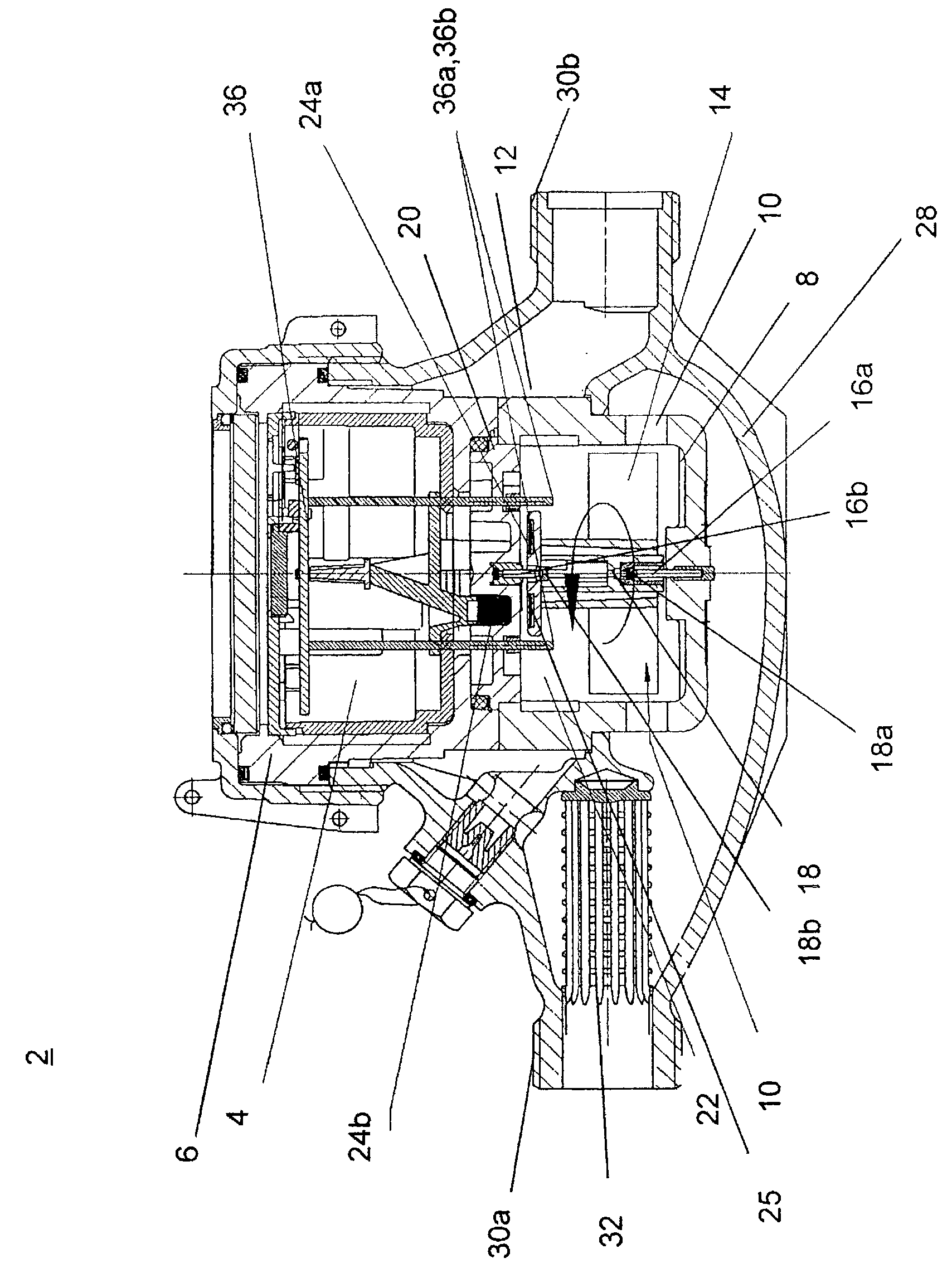
[0035] exist figure 1 Among them, the multi-jet impeller water meter 2 designed according to the example of the present invention is shown in cross-sectional view. This capacity meter 2 has: an electronic calculation unit 4, which is arranged in a calculation unit housing 6 designed in the form of a bucket; Body 8 , which has an inflow line 10 and an outflow line 12 , in which a measuring body designed as an impeller 14 is rotatably arranged. The measuring application housing 8 of bucket-shaped design has a bucket-shaped bottom, wherein the first end 18 a of the impeller shaft 18 which receives the impeller 14 is rotatably arranged in the first support 16 a. Furthermore, the first support plate 20 has a second support 16b in which the second end 18b of the impeller shaft 18 is rotatably arranged and which upwardly delimits the measurement use housing 8 and together with the measurement The original measuring chamber 22 is enclosed by the housing 8 .

[0036]The housing 8 us...


PUM


Abstract

The invention relates to a volume meter (2) for flowing media, in particular liquids, comprising a calculating unit (4), a volume measurement device with a measurement chamber (20) that is flown through by a medium and has at least one inlet (10) and at least one outlet (12), and a counter system, characterized in that a sensor arrangement (36) is provided which monitors and / or detects a predefined specific parameter of the respective flowing medium and that a selective coupling or decoupling between the counter system and the calculating unit (4) is produced depending on the parameters. The invention further relates to a method for carrying out the method with an aforementioned volume meter (2).

Description

technical field [0001] The invention relates to a volumetric meter for flowing media, in particular for liquids such as water, and a corresponding method for calculating volumes in which, for example, air-like Undesirable miscalculation results caused by air bubbles. Background technique [0002] Known volumetric meters for liquids, in particular multi-jet vane meters designed as suction pumps for dry gases, generally comprise a calculation unit, one or more pulse sensors and a measuring user, wherein the impeller and the impeller shaft is rotatably held on two brackets. In addition, at least one pulse transmitter is provided, which is connected to the impeller shaft and rotates with the impeller and works with at least one pulse sensor in such a way that the pulse transmitter generates a pulse signal when traversing the sensor region in the sensor. . In this case, any signal with a finite duration and a predetermined pulse height or a predetermined curve is considered to...

Claims


Application Information

Patent Timeline
Patent Type & Authority Applications(China)
IPC IPC(8): G01F1/075
CPCG01F1/075
Inventor 鲁迪·基塞尔拉尔夫·博特吕迪格·阿梅斯
Owner ELSTER MESSTECHNIK GMBH
Learn More