Disc brake for hinge sliding type vehicle

A brake and sliding technology, applied in the direction of brakes, vehicle parts, brake components, etc., can solve the problems of cost increase, weight increase, and number of parts, etc., to achieve low cost, low miniaturization, and reduce the number of parts Effect

Active Publication Date: 2009-11-18
HITACHI ASTEMO LTD
View PDF1 Cites 4 Cited by
  • Summary
  • Abstract
  • Description
  • Claims
  • Application Information

AI Technical Summary

Problems solved by technology

[0004] However, although the above-mentioned Patent Document 1 can apply a well-balanced pressing force to the friction lining and can suppress uneven wear of the friction lining, the number of pistons increases, the number of parts increases, and the weight also increases, and the formation of liquid passage holes is also difficult. trouble, rising costs

Method used


Image

  • Disc brake for hinge sliding type vehicle
  • Disc brake for hinge sliding type vehicle
  • Disc brake for hinge sliding type vehicle

Examples


Embodiment Construction

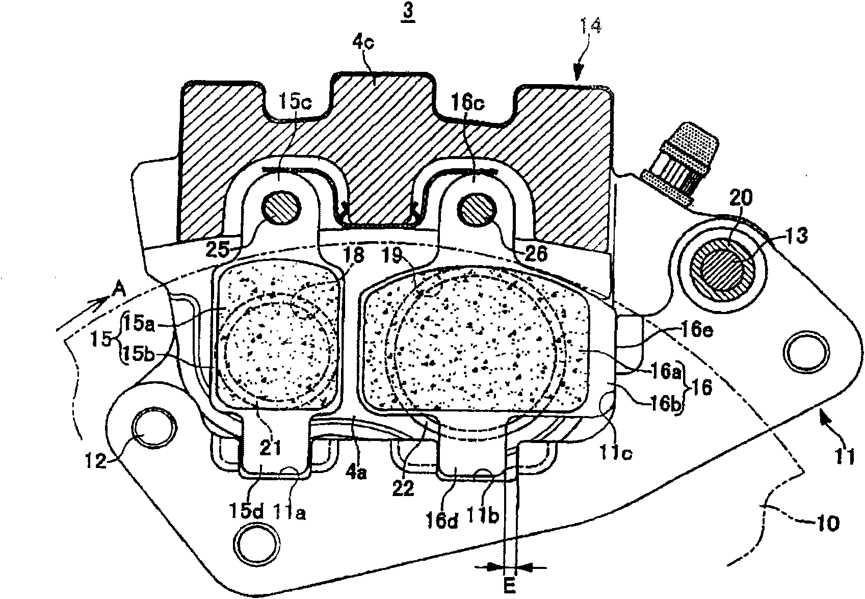
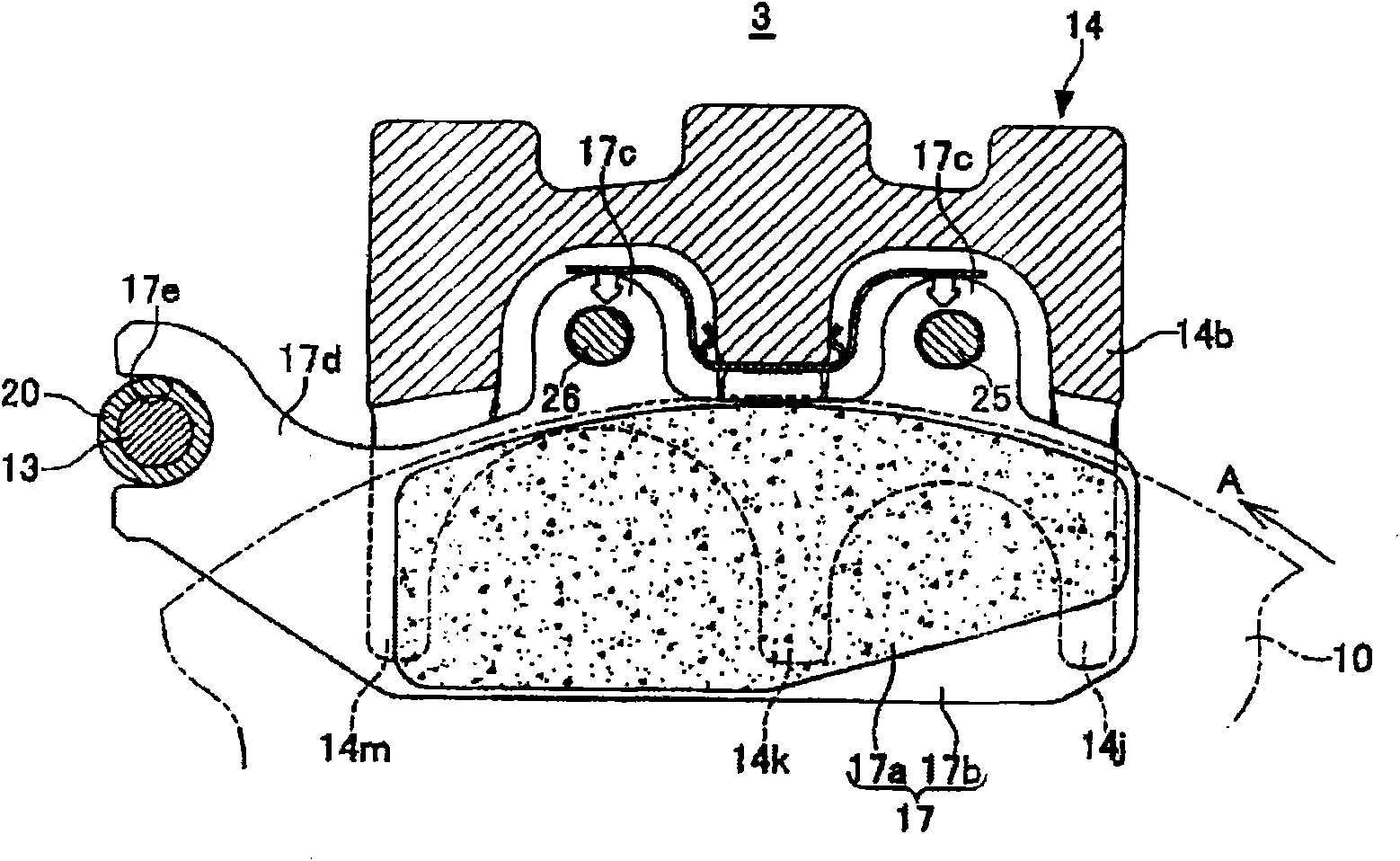
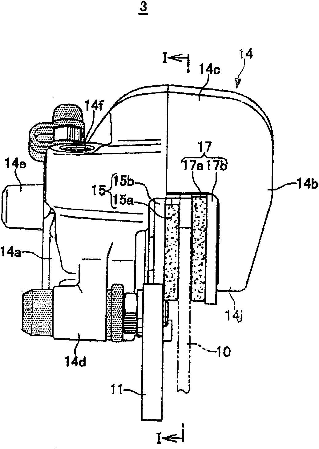
[0046] Figure 1 to Figure 8 It is a figure showing an embodiment of the hinge slide type vehicle disc brake of the present invention, figure 1 yes image 3 I-I sectional view, figure 2 yes Figure 4 II-II sectional view, image 3 is the side view of the disc brake, Figure 4 is the top view of the disc brake, Figure 5 yes Figure 4 The V-V sectional view, Image 6 yes Figure 8 The VI-VI sectional view, Figure 7 yes Figure 8 Sectional view of VII-VII, Figure 8 It is a system diagram of a disc brake device to which the disc brake of the present invention is applied. Arrow A in the figure indicates the rotation direction of the disc rotating body when the vehicle is running forward, and the disc turning-in side and the disc turning-out side used in the following description refer to the situation when the vehicle is moving forward.

[0047] Such as Figure 8 As shown, the lever-type handlebar brake device 1 of this embodiment has: an independent system brake sys...


PUM


Abstract

The present invention provides a disc brake for hinge sliding type vehicle, which is a disc brake for a double-system hinge sliding type vehicle. While a stable braking force is ensured, the number of accessories is restrained to low. The light weight and cost reduction can be obtained. Furthermore the uneven abrasion of the friction gasket can be reduced maximumly. One counteraction side friction gasket (17) is configured between a disc body (10) and the front surfaces of a plurality of counteraction claws (14j, 14k, 14m) at the counteraction part side of a tong body (14). A single system friction gasket (16) is configured between the disc body (10) and the front surface of a single system piston (22) at the action part side. A linking system friction gasket (15) is configured between the disc body (10) and the front surface of a linking system piston (21).

Description

technical field [0001] The present invention relates to a disc brake for a hinge-sliding type (pinsride type) vehicle. System type hinge slide type disc brake for vehicles. Background technique [0002] Conventionally, the disc brake for a hinge-sliding type vehicle as a double system has more than three cylinder holes in the action part, and at least two deep bottom cylinder holes including two side parts are opposed to other shallow bottom cylinder holes that are shallower than it. The caliper body is arranged symmetrically to the center line in the radial direction of the disk, and the liquid passage hole of the deep bottom cylinder hole is pierced in the bottom wall part of the shallow bottom cylinder hole, so that the hydraulic path of the caliper body is divided into two systems (for example, refer to Patent Document 1). [0003] Patent Document 1: (Japanese) Publication No. 7-49085 [0004] However, although the above-mentioned Patent Document 1 can apply a well-bal...

Claims


Application Information

Patent Timeline
IPC IPC(8): B60T1/06
Inventor 小山彻青沼亨草野俊博波多腰弦一
Owner HITACHI ASTEMO LTD
Why Eureka
Try Eureka