Manual lifting self-shooting bar of compact camera

A selfie stick and camera technology, applied in the direction of camera, camera body, supporting machine, etc., can solve the problem that the shooting effect is difficult to keep upright

Inactive Publication Date: 2009-11-18
沈金钟
View PDF0 Cites 21 Cited by
  • Summary
  • Abstract
  • Description
  • Claims
  • Application Information

AI Technical Summary

Problems solved by technology

This is not only very convenient, but also th

Method used


Image

  • Manual lifting self-shooting bar of compact camera
  • Manual lifting self-shooting bar of compact camera
  • Manual lifting self-shooting bar of compact camera

Examples


Embodiment Construction

[0010] The present invention is described in detail below in conjunction with accompanying drawing:

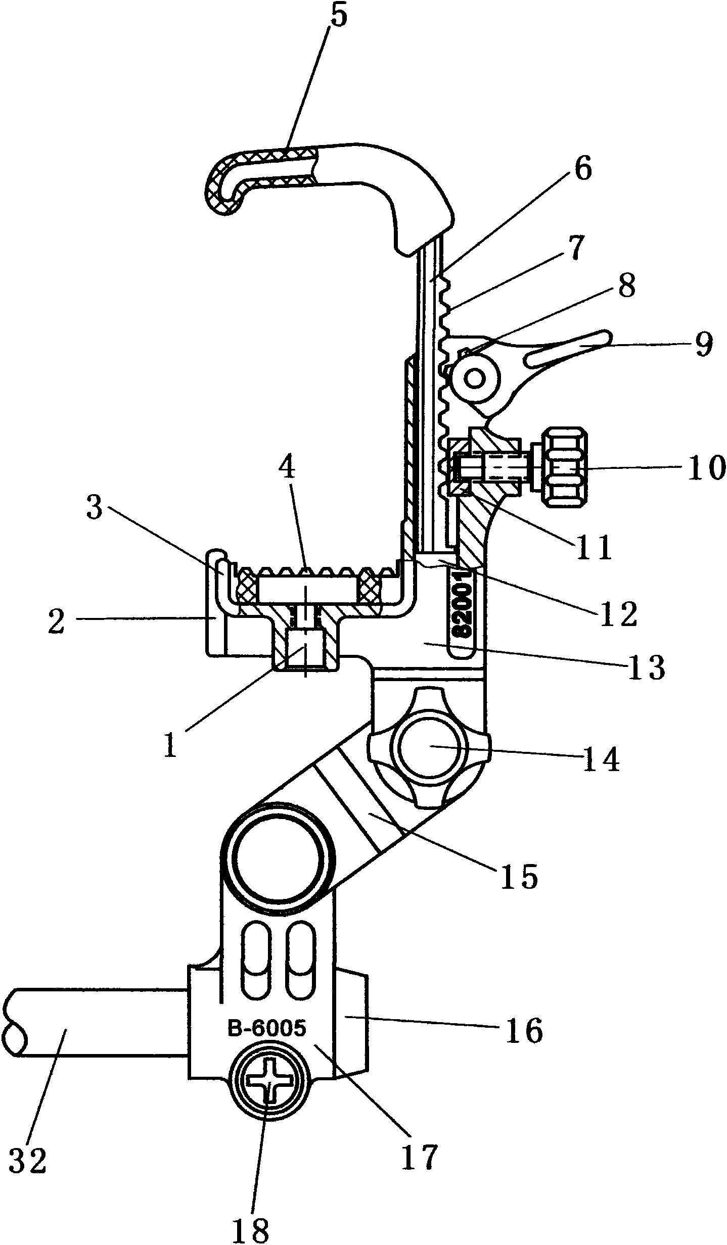
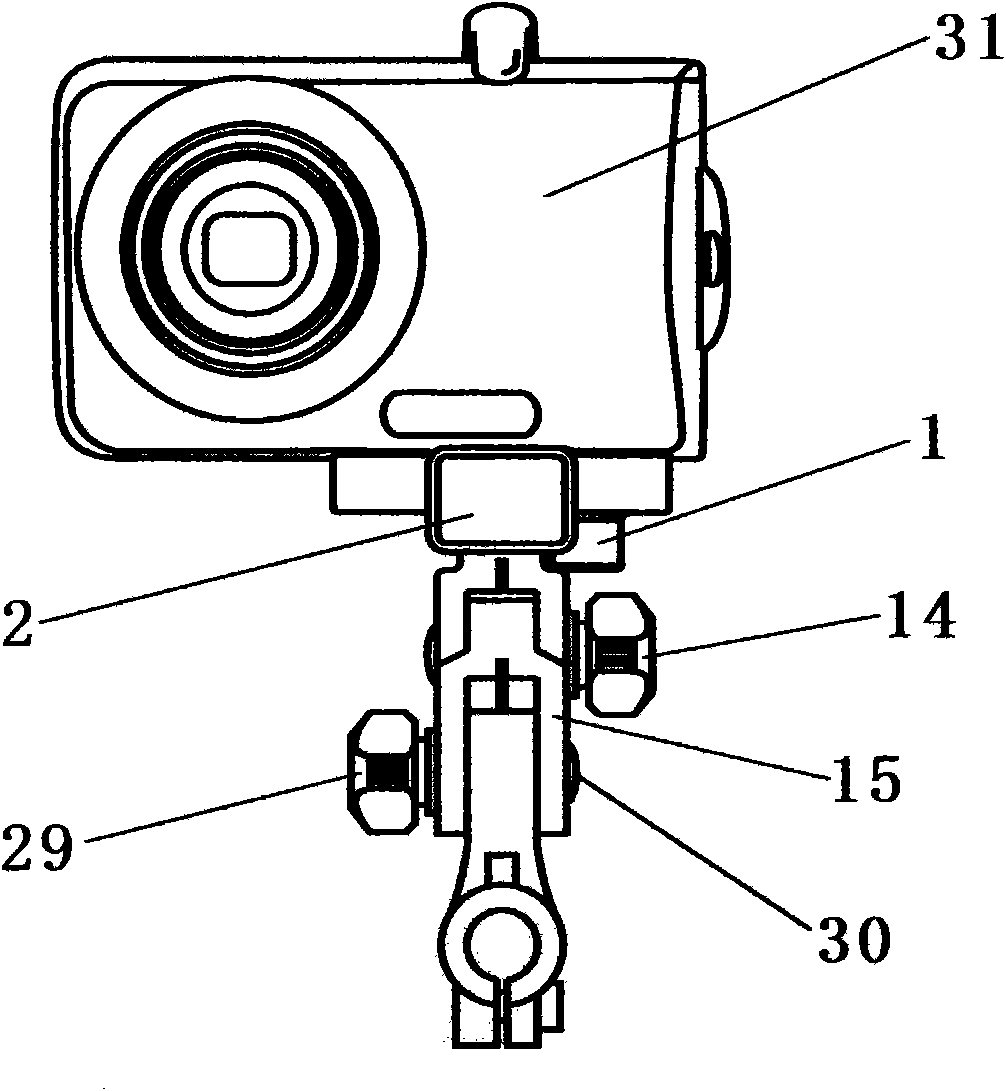
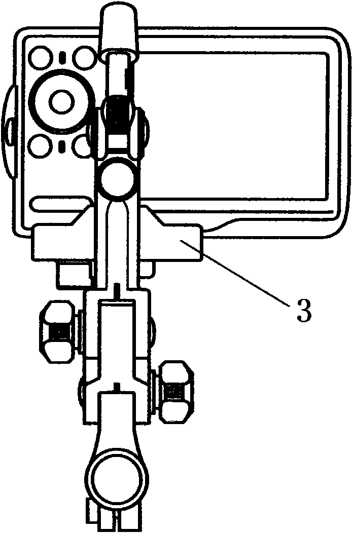
[0011] like figure 1 , figure 2 , image 3 , Figure 4 , Figure 5 , Image 6 Shown, the present invention mainly is made of clamping pan-tilt and telescoping rod, grip and shutter cable etc. There is a hook cavity 12 for the set hook 6 behind the main part 13 of the snap-fit ​​pan / tilt, and the hook rod cavity 12 is provided with the hook 6 and the locking mechanism locking pressure 11 and the hook locking knob 10 for locking the hook 6 . There is a hook locking wrench 9 on the top of the main part 13 of the clamping head. After the hook locking wrench 9 is moved, the hook locking wrench teeth 8 and the hook rack 7 drive the locking structure 6 to lock the camera 31 . The card structure 6 is except that one side of the hook bar is provided with a grab tooth bar 7, and also has a rubber soft cover 5 at the crotch section. The middle part of card mounting pan-tilt mai...


PUM


Abstract

The invention aims to provide a manual lifting self-shooting bar of a compact camera, which has the characteristics of small volume, simple structure, convenient use, and the like. When people need to shoot, the compact camera can be clamped on a camera clamping tripod head of the manual lifting self-shooting bar, and after a shutter release interface positioned on the lower part of the camera clamping tripod head is connected with a shutter release, people can stretch a telescopic link to a needed length to be locked, regulate the angle of the compact camera again and well set the compact camera so as to independently shoot.

Description

(1) Technical field: [0001] The invention relates to a hand-held selfie stick for a small camera. (two) background technology: [0002] At present, when people are traveling or taking pictures with friends, they either turn to others for help or use a tripod or place the camera at a place where they can take a selfie. This is not only very convenient but also difficult to keep the effect of shooting. (3) Contents of the invention: [0003] The purpose of the present invention is to provide a selfie stick with a small camera, which has the characteristics of small size, simple structure, and convenient use. When people need to take a selfie, the camera can be mounted on the camera mounting platform of the present invention , After connecting the shutter cable through the shutter cable interface at the lower part of the gimbal, pull the telescopic rod to the required length and lock it, then adjust the camera angle and set the camera to take a selfie. [0004] The present ...

Claims


Application Information

Patent Timeline
IPC IPC(8): G03B17/38F16M11/00
Inventor 沈金钟
Owner 沈金钟
Why Eureka
Try Eureka