
Circuit base plate and light-emitting diode encapsulation

A technology of light-emitting diodes and circuit substrates, which is applied in the direction of circuits, electrical components, and electrical solid devices, can solve the problems of high production costs of conductive structures, and achieve the effect of low production costs and high arrangement density

Active Publication Date: 2009-11-18
EVERLIGHT ELECTRONICS (CHINA) CO LTD
View PDF0 Cites 9 Cited by
  • Summary
  • Abstract
  • Description
  • Claims
  • Application Information

AI Technical Summary

Problems solved by technology

Therefore, the fabrication cost of the conductive structure is higher

Method used


Image

  • Circuit base plate and light-emitting diode encapsulation
  • Circuit base plate and light-emitting diode encapsulation
  • Circuit base plate and light-emitting diode encapsulation

Examples


Embodiment Construction

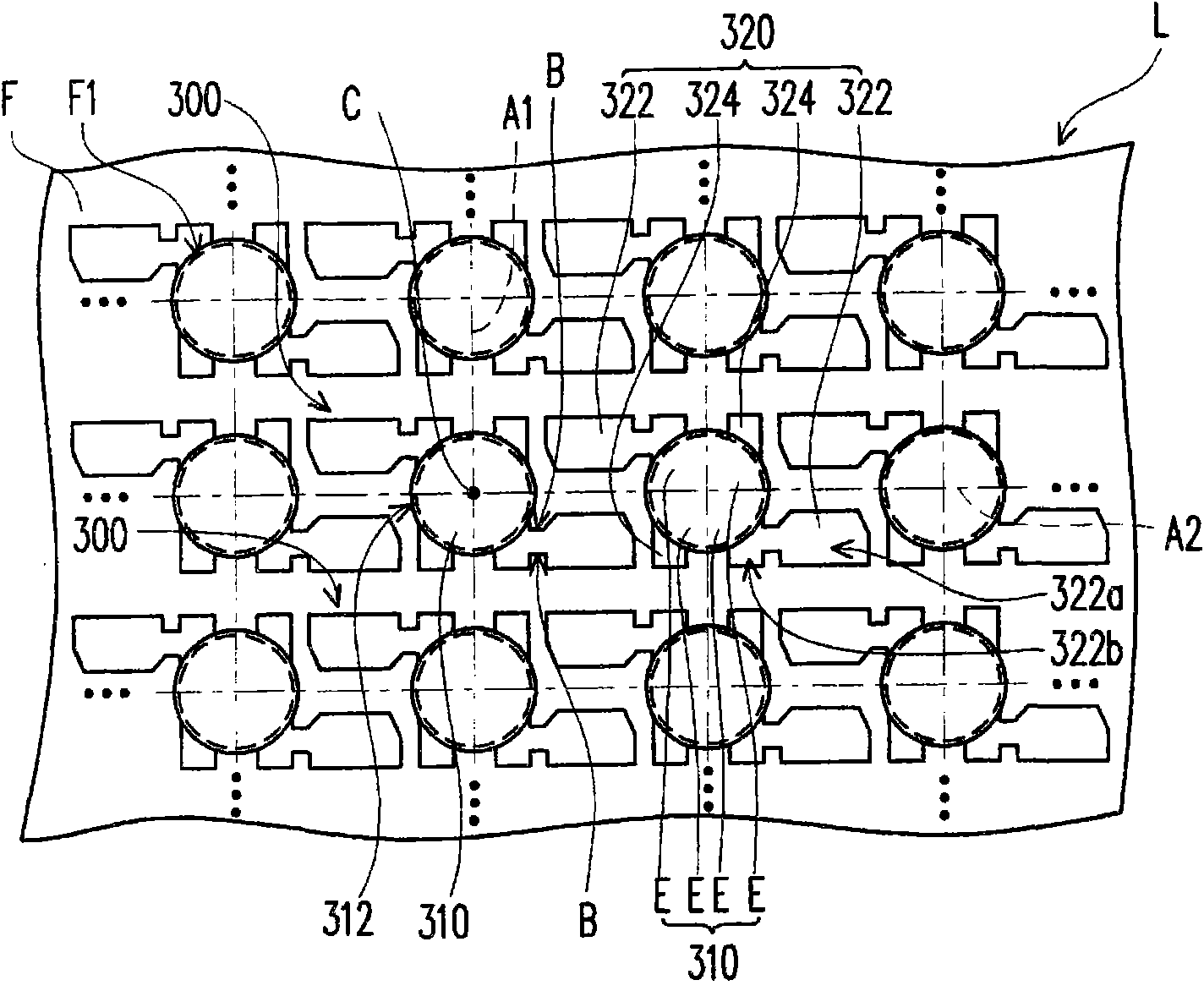
[0056] Figure 3A and Figure 3B is a schematic diagram of a circuit substrate according to an embodiment of the present invention, Figure 4 ~ Figure 11 for Figure 3A Schematic diagrams of various variations of circuit substrates.

[0057] Please refer to Figure 3A , the circuit substrate L of this embodiment includes a base layer F and a plurality of pin units 300 arranged in an array, wherein the pin units 300 are all configured on the base layer F, and the pin units 300 arranged in an array refer to the pins The units 300 are arranged on the base layer F in multiple rows and multiple columns. The base layer F has a plurality of counterbores F1. Each pin unit 300 includes a shared terminal 310 and at least three pins 320 , and in this embodiment, each pin unit 300 has four pins 320 . The shared terminal 310 is divided into a plurality of electrodes E connected to each other. The pins 320 extend outward from the edge of the shared terminal 310 , and each pin 320 ext...


PUM


Abstract

The invention relates to a circuit base plate which comprises a base layer and a plurality of pin units, wherein the pin units form array arrangement, the base layer is provided with a plurality of counter bores, and the pin units are configured on the base layer; each pin unit comprises a share terminal and at least three pins; a share terminal area is divided into a plurality of poles connected with each other; the pins outwards extend from the edges of the share terminals, and each pin outwards extends from the edge of one of the poles; and the counter bores respectively expose the share terminals of the pin units.

Description

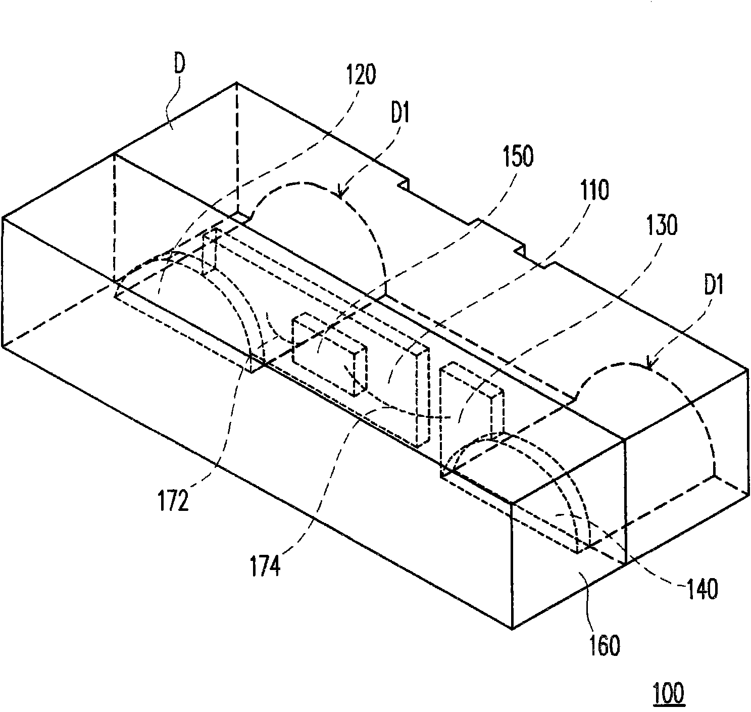
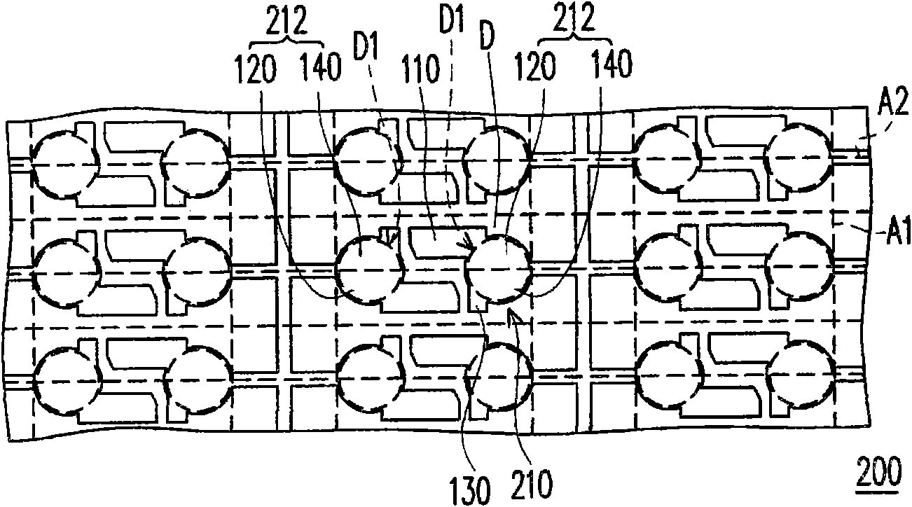
technical field [0001] The present invention relates to a circuit substrate and a light emitting diode package, and in particular to a circuit substrate and a light emitting diode package with relatively low production costs. Background technique [0002] Compared with traditional light bulbs, light-emitting diodes have the characteristics of small size, long life, power saving, and no mercury pollution. Therefore, as the luminous efficiency of light-emitting diodes continues to increase, light-emitting diodes have gradually replaced fluorescent lamps and incandescent lamps in some fields. For example, light sources for scanners that require high-speed response, backlights for liquid crystal displays (LCDs), light sources for instrument panels, light sources for traffic lights, and certain lighting devices have all used light-emitting diodes. . [0003] figure 1 It is a three-dimensional schematic diagram of a known light emitting diode package. figure 2 is a schematic ...

Claims


Application Information

Patent Timeline
Patent Type & Authority Applications(China)
IPC IPC(8): H01L23/488H01L23/498H01L33/00
CPCH01L24/97H01L2224/48091H01L2224/48247H01L2924/12041
Inventor 邹文杰
Owner EVERLIGHT ELECTRONICS (CHINA) CO LTD
Learn More