Energy saving device

A technology of energy-saving device and control unit, applied in the direction of electrical program control, program control in sequence/logic controller, etc., can solve the problems of unsensed load, real-time response, consumption of excess energy, etc.

Inactive Publication Date: 2009-11-25
王天庆 +3
View PDF6 Cites 0 Cited by
  • Summary
  • Abstract
  • Description
  • Claims
  • Application Information

AI Technical Summary

Problems solved by technology

[0004] Another example is U.S. Patent No. US4,443,750 which discloses an "Energy Saving Motor Speed ​​Controller (ENERGY SAVING MOTOR SPEED CONTROLLER)", as described in the patent figure 1 As shown, it uses a six-step control signal generator (SIX STEP CONTRON SIGNALCONTROLLER) to generate a control signal to its corresponding drive circuit to control the speed of the motor; but as mentioned above, its load is connected in series after the motor, and the patent does not The parameters of the motor are not sensed, so naturally it is impossible to respond in real time to the change of the load, so that the load can maintain continuous active state operation, so as to achieve the effect of energy saving
[0005] Another example is U.S. Patent No. US6,462,461B1, which discloses a "Circuit for Correcting the Operation of Ultrasonic Generators (CIRCUITRY TO MODIFY THE OPERATION OFULTRASONIC GENERATORS)". The sound wave generator operates; but as mentioned above, the patent does not sense the parameters of the load, so naturally it is impossible to respond in real time to changes in the load, so that the load can maintain a continuous active state of operation to achieve energy-saving effects
[0006] Another example is U.S. Patent No. US4,996,965, which discloses an "electronic engine control method and system for internal combustion engines (ELECTRONIC ENGINE CONTROL METHOD AND SYSTEM FOR INTERNAL COMBUSION ENGINES)", as shown in Figure 6 of the patent, the operation of the internal combustion engine includes One stop (REST) ​​state, and one running state, so when switching from the stop state to the running state, it needs to consume excess energy, and this patent does not sense the parameters of the internal combustion engine, so it is naturally impossible to respond to load changes in real time response to keep the load running at a constant
[0007] Another example is U.S. Patent No. US6,177,739B1, which discloses a kind of "power supply for equipment with energy-saving mode, energy-saving control device and energy-saving image forming device with the power supply (ELECTRICPOWER SOUCE FOR EQUIPMENT HAVING POWER SAVING MODE, POWER SAVING CONTROL DEVICE AND IMAGE FORMING APPARATUS HAVING THE POWER SOURCE)", as shown in Figure 6 of the patent, it has a central processing unit (CPU), a timer (timer) and a power supply, the central processing unit can reduce the output in the energy-saving mode To achieve the purpose of energy saving; however, this patent does not sense the parameters of the load, so naturally it is impossible to respond in real time to the change of the load so as to maintain the constant operation of the load
[0008] Another example is U.S. Patent No. US7,315,097B2, which discloses a "energy-saving control method and device in an electronic device, and an energy-saving electronic device (POWER SAVING CONTROL METHODAND DEVICE IN ELECTRONIC DEVICE, AND POWER SAVING ELECTRONIC DEVICE)", such as the patent figure 1 As shown, it has a latch (LATCH), when the switch (SW1) is open (OFF), the latch can provide current from a power supply to the load to achieve the purpose of energy saving; Therefore, it is impossible to respond in real time to changes in the load so that the load can maintain a constant operation.

Method used


Image

  • Energy saving device
  • Energy saving device
  • Energy saving device

Examples


Embodiment Construction

[0045] In order to further understand the structure, features and purpose of the present invention, detailed descriptions of the accompanying drawings and preferred specific embodiments are as follows.

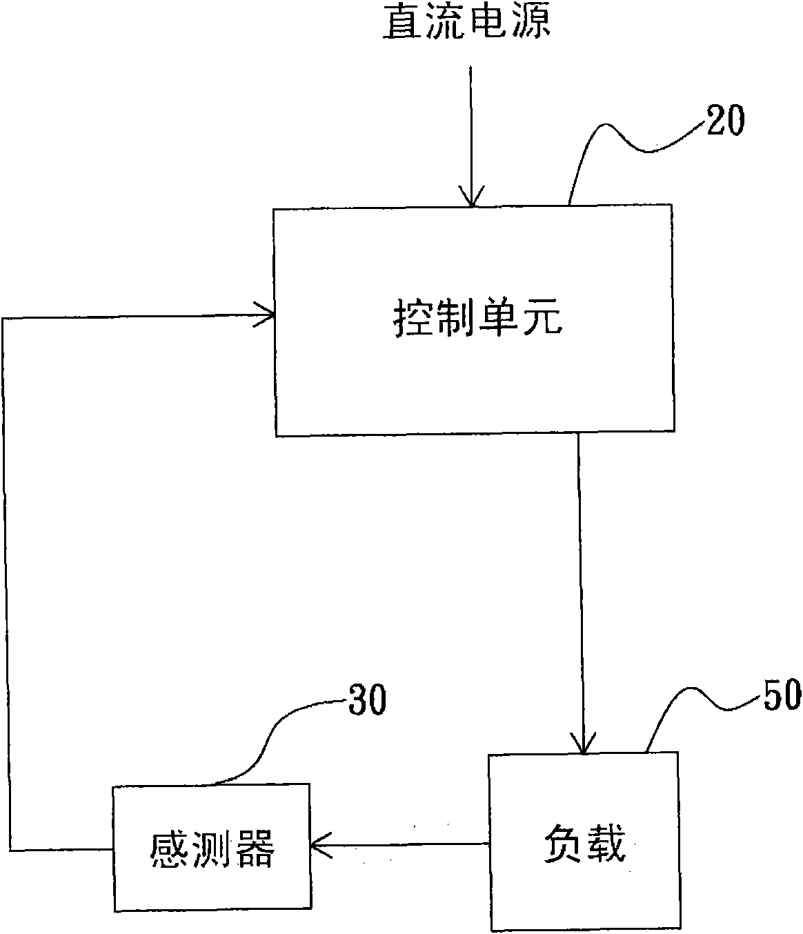
[0046] Please refer to figure 1 , which shows a schematic block diagram of the energy-saving device of the present invention.

[0047] As shown in the figure, the energy-saving device of the present invention includes: a control unit 20; and at least one sensor 30 combined.

[0048] Wherein, one end of the control unit 20 is coupled to a DC power source, such as but not limited to a battery or storage battery, and the other end is coupled to a load 50, which has at least one preset parameter inside, and the preset parameter includes, for example, but Not limited to temperature, noise, rotational speed, vibration, voltage, current or power, the system operator can pre-input the preset parameters according to the parameters to be monitored, for example, when it is desired to ma...


PUM


Abstract

The invention relates to an energy saving device which comprises a control unit and at least one sensor, wherein one end of the control unit is coupled to a DC power supply and the other end is coupled to a load, and the control unit is internally provided with at least one preset parameter; one end of the sensor is coupled to the load and the other end is coupled to the control unit, and the sensor can sense at least one parameter during the operation of the load; when the DC power supply passes through the control unit, the parameter sensed by the sensor is converted by the control unit and compared with the preset parameter, and the control unit can output a control signal to the load so as to maintain the stability of the load and the operation of a continuous active power state so that the energy saving effect is achieved.

Description

technical field [0001] The present invention relates to an energy-saving device, especially a device that can feed back the load status to the control unit through a sensor, and the control unit outputs a control signal after comparing with a preset parameter to keep the load running stably, so as to achieve Energy-saving devices for energy-saving purposes. Background technique [0002] According to the general air conditioner, it usually has a temperature sensor. When the temperature sensed by the temperature sensor is higher than the default value, the compressor starts to run to reduce the indoor temperature. Or, although the variable frequency air conditioner claims to have a constant temperature and energy-saving effect compared with the traditional air conditioner, the compressor is still on or off, and the starting current is usually several times the operating current, so it has not achieved the desired effect. Energy saving state. [0003] Another example is a gen...

Claims


Application Information

Patent Timeline
Patent Type & Authority Applications(China)
IPC IPC(8): G05B19/04
Inventor 王天庆王世仁傅小娟王立成
Owner 王天庆
Why Eureka
Try Eureka