Composite retarder braking orbit

A compound brake and retarder technology, which is applied in the direction of track brakes, railway car body parts, transportation and packaging, etc., can solve problems such as the inability to meet the function and performance of the retarder, and the poor effect, so as to change the quality of the working environment and reduce Equipment maintenance personnel and engineering quantity, and the effect of improving mechanical characteristics

Inactive Publication Date: 2009-12-02
北京人和路通科技有限公司
View PDF0 Cites 1 Cited by
  • Summary
  • Abstract
  • Description
  • Claims
  • Application Information

AI Technical Summary

Problems solved by technology

In the past, many researches on eliminating noise pollution were mainly carried out from the mechanical point of view, trying to achieve the goal by reducing the overall vibration and noise of the retarder, but the results were not good.
There are also those who want to use materials with noise reduction performance to solve the noise, but they cannot meet the function and performance of the retarder

Method used


Image

  • Composite retarder braking orbit
  • Composite retarder braking orbit
  • Composite retarder braking orbit

Examples


Embodiment Construction

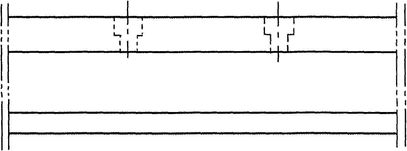
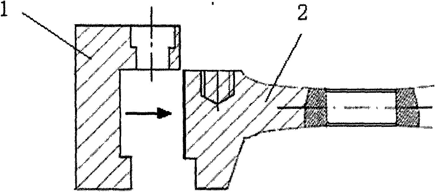
[0014] The brake rail of the present invention is composed of two parts, the noise reduction plate 1 and the base rail 2. The noise reduction plate 1 is in the shape of a right angle, and includes a fixed side 3 and a braking side 4 at right angles. The fixed side 3 and the base rail 2 are provided with Through the through hole 5 , the bolt is passed through the through hole 5 , so that the noise reduction plate 1 is fixed on the base rail 2 , and the braking edge 4 is tightly attached to the base rail 2 .

[0015] The present invention has the following advantages:

[0016] 1. Simplify the maintenance process and reduce the maintenance engineering volume. The installation structure of the present invention can conveniently replace the noise reduction plate, and there is no need to disassemble the brake rail when replacing the noise reduction plate. Access skylights for hump operations for maintenance work.

[0017] 2. Improve the stress state of the fastener, increase the s...


PUM


Abstract

The invention relates to a composite retarder braking orbit for eliminating the high frequency noise generated by the friction of a retarder braking orbit; wherein, the composite retarder braking orbit comprises a noise reduction board and a base rail, the noise reduction board is right angle type containing a right-angled clamped edge and a brake edge, through-holes are arranged on the clamped edge and the base rail, and a bolt penetrates the through-holes so that the noise reduction board can be fixed on the base rail and the brake edge is closely attached to the base rail.

Description

technical field [0001] The invention relates to retarder technology, in particular to a novel retarder composite brake rail. Background technique [0002] The retarder is a speed-regulating device widely used in my country's railway marshalling yards to control the speed of slipping vehicles. At present, the brake rail used on the domestic retarder is a 60Kg / m steel rail, and the retarder is driven by a hydraulic cylinder or an air cylinder to brake during work. Clamp, so that the brake rail fixed on the brake caliper clamps the wheel of the vehicle, and the purpose of controlling the speed of the vehicle is achieved through the sliding friction between the side of the wheel tire and the brake rail. The working principle of this retarder can be found in " 7501 Vehicle Reducer" (edited by the Communication Signal Research Institute of the Ministry of Railways Academy of Sciences, China Railway Press, 1980 edition). The operation process is accompanied by unbearable harsh high-...

Claims


Application Information

Patent Timeline
Patent Type & Authority Applications(China)
IPC IPC(8): B61K7/02
Inventor 周沛王纬中
Owner 北京人和路通科技有限公司
Why Eureka
Try Eureka