
Efficient wallboard forming machine

A molding machine and wall panel technology, which is applied in the direction of ceramic molding machines, auxiliary molding equipment, mold fixing devices, etc., can solve the problems of end face template installation position deviation, unqualified, ball falling off, etc.

Pending Publication Date: 2020-06-19
DAYUAN CONSTR GRP
View PDF0 Cites 0 Cited by
  • Summary
  • Abstract
  • Description
  • Claims
  • Application Information

AI Technical Summary

Problems solved by technology

[0005] 1. There is no positioning and fixing device for the glass fiber mesh. When pouring, the glass fiber mesh needs to be tightened manually, which not only wastes manpower, but also often causes the mesh to shift or fall.
[0006] 2. There is no positioning device for the end formwork, and the installation position of the end formwork often deviates, resulting in errors in the height and dimension of the wall panels and unqualified
[0007] 3. The guide rail of the formwork opening and closing movement uses a ball slider guide rail pair, which often causes the balls to fall off when encountering debris such as cement, and the failure rate is high

Method used


Image

  • Efficient wallboard forming machine
  • Efficient wallboard forming machine
  • Efficient wallboard forming machine

Examples


Embodiment Construction

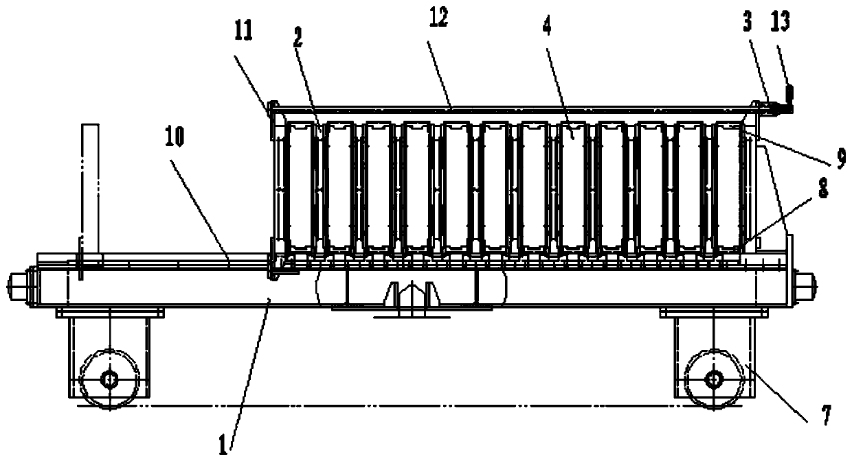
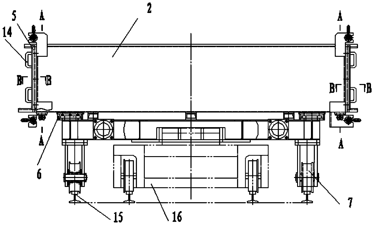
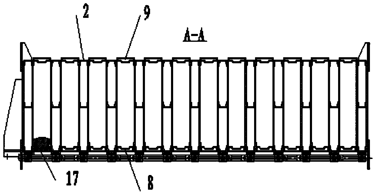
[0025] A high-efficiency wallboard molding machine, which includes a frame 1, a plurality of templates 2, a plurality of end templates 4 and a plug-in plate 5, two template guide rails 10 are fixedly installed on the frame along the extension direction, and the template at the left end is fixed Installed on the frame, the inner and outer sides of the bottom of the remaining templates are respectively clamped on the template guide rails through the slider 6, and a lower mold strip 8 is vertically placed above the template guide rails between each two templates. The sides are snapped into the end formwork and fixed by the first positioning pin 17, and the top of the end formwork is snapped onto the upper mold bar 9. There are pin holes corresponding to each other between the formwork and the end formwork, and the pin holes are inserted with the first Two positioning pins 18, the inner and outer sides of the template are respectively provided with slots 19 near the left and right ...


PUM


Abstract

The invention relates to the technical field of production of wallboard forming machines, in particular to an efficient wallboard forming machine. The efficient wallboard forming machine comprises a machine frame, a plurality of formworks, a plurality of end face formworks and an insertion board. Two formwork guide rails are fixedly installed on the machine frame, the left end formwork is fixedlyinstalled on the machine frame, and the inner sides and outer sides of the bottoms of the rest of the formworks are respectively clamped on the formwork guide rails through sliding blocks, one lower mold strip is longitudinally placed between each two formworks, the inner sides and the outer sides of the lower mold strips are respectively clamped to the end face formworks and fixed by first positioning holes. Upper mold strips are clamped to the tops of the end face formworks, mutual corresponding pin holes are formed between the formworks and the end face formworks, and second positioning pins are inserted in the pin holes. Insertion grooves are formed in the inner sides and the outer sides of the formworks, glass fiber mesh cloth is laid on the left end faces and the right end faces of the formworks, and the inner ends and the outer ends of the glass fiber mesh cloth are clamped into the insertion grooves, and fixed by insertion plates in the insertion grooves. According to the efficient wallboard forming machine, the mesh cloth is conveniently fixed, the end face formworks are conveniently positioned, and the failure rate is low.

Description

technical field [0001] The invention relates to the technical field of wallboard forming machine production, in particular to a high-efficiency wallboard forming machine. Background technique [0002] With the country's vigorous promotion of prefabricated buildings, various new types of prefabricated panels have emerged. These prefabricated new panels are poured and formed by a mold forming machine, that is, specific lightweight cement slurry is poured into the mold cavity of the forming machine, and cured and formed after curing. [0003] Existing wall panel molding machines are mainly aimed at hollow panels or solid foamed cement panels, and there is no mold molding machine for composite panels with a sandwich layer and glass fiber grid cloth. [0004] The disadvantages of the existing wall panel forming machine are: [0005] 1. There is no positioning and fixing device for the glass fiber mesh. When pouring, the glass fiber mesh needs to be tightened manually, which not...

Claims


Application Information

Patent Timeline
IPC IPC(8): B28B7/00B28B23/00B28B17/00
CPCB28B7/0002B28B7/0014B28B7/0038B28B17/00B28B23/0056
Inventor 王连兴回丽丽甄少华苏娜李亚奇庞维聪杨松源苑太海刘志光姜鸥
Owner DAYUAN CONSTR GRP
Learn More