Eureka AIR delivers breakthrough ideas for toughest innovation challenges, trusted by R&D personnel around the world.

Box pallet

A pallet and box-type technology, which is applied in the field of box-type pallets, can solve problems such as insufficient installation, damaged boards, and inability to disassemble and remove, and achieve the effect of preventing net damage, loosening, deformation or folding

Active Publication Date: 2011-08-10
SAFT GREEN ENG
View PDF1 Cites 1 Cited by
  • Summary
  • Abstract
  • Description
  • Claims
  • Application Information

AI Technical Summary

Problems solved by technology

[0008] First, the above-mentioned box-type pallets are carried by forklifts or vehicles, but no effort has been made to lift and lower the cranes at the project site
[0009] Therefore, in the case of lifting by a forklift, other special work is required each time, and since the hook at the tip of the wire of the forklift is hung on the metal net used to form the panel, the panel may be damaged.
[0010] Second, it is assembled into a box shape during use, and a firm locking mechanism is required to maintain the box shape, but this kind of device is not necessarily sufficient, and the state of the box cannot be maintained, and there is a danger of deformation depending on the situation
[0011] Third, since the front, rear, left, and right panels assembled in a box shape cannot be disassembled and removed, it is necessary to carry out and load goods inside the assembled box shape, which is troublesome in operation

Method used


Image

  • Box pallet
  • Box pallet
  • Box pallet

Examples


Embodiment Construction

[0043] Next, an embodiment of the present invention will be described based on the drawings.

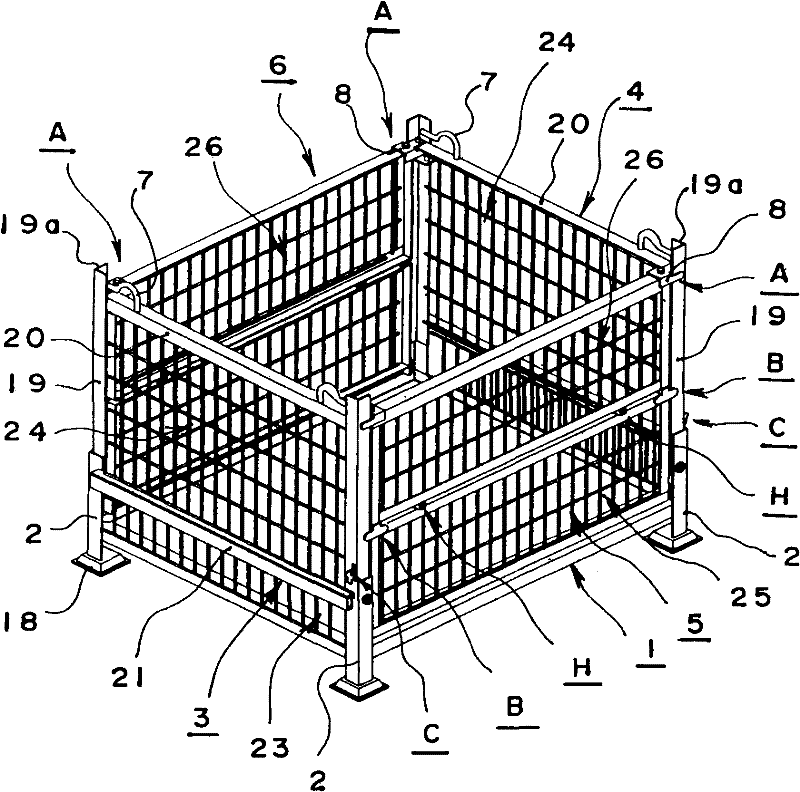
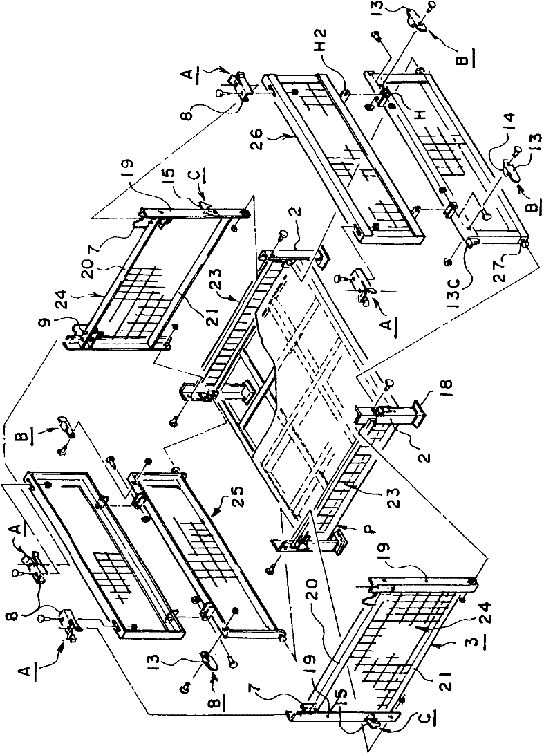
[0044] like figure 1As shown, the box-type pallet of the present invention has: a bottom plate 1, a foot body 2 for stacking upright at the four corners of the bottom plate 1, and is axially supported between a pair of foot bodies 2 and 2 on the left side to be able to freely The left plate 3 that rotates, the right plate 4 that is pivotally supported to be able to rotate freely between the front and rear pair of feet 2,2 on the right side, is pivotally supported to be able to rotate between the left and right pair of feet 2,2 on the front side. The freely rotatable double-fold front plate 5 and the freely rotatable double-fold rear plate 6 are also axially supported between the left and right pair of leg bodies 2 and 2 on the rear side. Fold the front and rear panels 5 and 6 in half and stack them on the bottom panel 1, then fold the left panel 3 and the right panel 4 and stack the...


PUM


Abstract

The box pallet is provided with a locking structure for maintaining the boxy shape and plates can be partially disassembled to convey goods inwards. The box pallet is provided with: a bottom plate, legs for stack erected at four corners of the bottom plate, a left plate which is supported by shaft to be rotatable between a pair of front and right legs at left side, a right plate which is supported by shaft to be rotatable between a pair of front and right legs at right side, a doubled-up front plate which is supported by shaft to be rotatable between a pair of left and right legs at front side and a doubled-up back plate which is supported by shaft to be rotatable between a pair of left and right legs at back side; the doubled-up front and back plates are simultaneously doubled up to be superposed on the bottom plate, the left plate and the right plate are folded to be superposed on the front plate and the back plate, the upper portions of the left plate and the right plate are each equipped with a hook fitting for steel wire handing of a crane, a first locking mechanism is respectively arranged between the upper portions of two ends of the left and right plates and between the upper portions of the front and back plates, a second locking mechanism is respectively arranged between the left plate and the right plate and between the front plate and the back plate, a third locking mechanism is respectively arranged between the leg at one end of the left plate and the leg on the left of the front side and between the leg at one end of the right plate and the leg on the right of the front side, and the above locking mechanisms are locked to erect the left, right, front and back plates so as to form the boxy shape.

Description

technical field [0001] The present invention relates to a freely collapsible box pallet, in particular to a box pallet that can be handled by a forklift or a crane. Background technique [0002] Usually, when loading and transporting components such as electronic devices to an assembly plant or loading and transporting materials and components for construction and civil engineering to a construction site, when moving mechanical parts produced by a machine factory to another assembly plant In some cases, box-shaped box pallets are used. [0003] For example, a box-type pallet has been developed. As shown in the following patent document 1, the box-type pallet is provided with a lower floor formed in the form of a metal mesh, front and rear panels and left and right panels that can be freely folded and erected on the front, rear, left, and right sides of the lower floor. The base plate and the legs for stacking are provided on the four corners of the lower base plate. [000...

Claims


Application Information

Patent Timeline
Patent Type & Authority Patents(China)
IPC IPC(8): B65D19/06B65D19/38B65D19/40
Inventor 增田晃
Owner SAFT GREEN ENG
Why Eureka
Eureka Blog
Learn More