Extracting device and method thereof

A cylinder and area technology, applied in the field of extraction devices for isolating impurities

Inactive Publication Date: 2012-07-25
TAIWAN MAGNETIC INNOVATION TECH
View PDF7 Cites 0 Cited by
  • Summary
  • Abstract
  • Description
  • Claims
  • Application Information

AI Technical Summary

Problems solved by technology

[0003] Therefore, there are above-mentioned inconveniences and problems in the known extracting device.

Method used


Image

  • Extracting device and method thereof
  • Extracting device and method thereof
  • Extracting device and method thereof

Examples


Embodiment Construction

[0074] The present invention will be further described below in conjunction with embodiment and accompanying drawing.

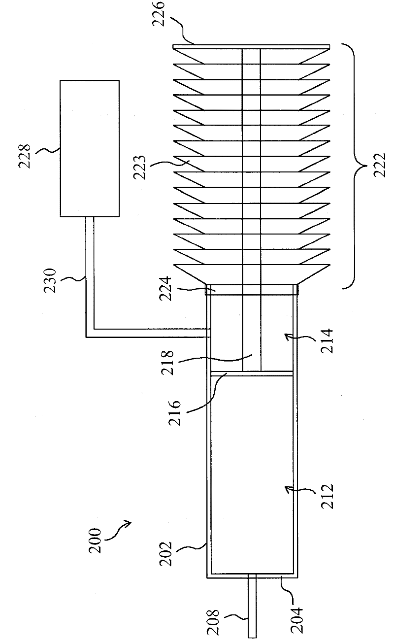
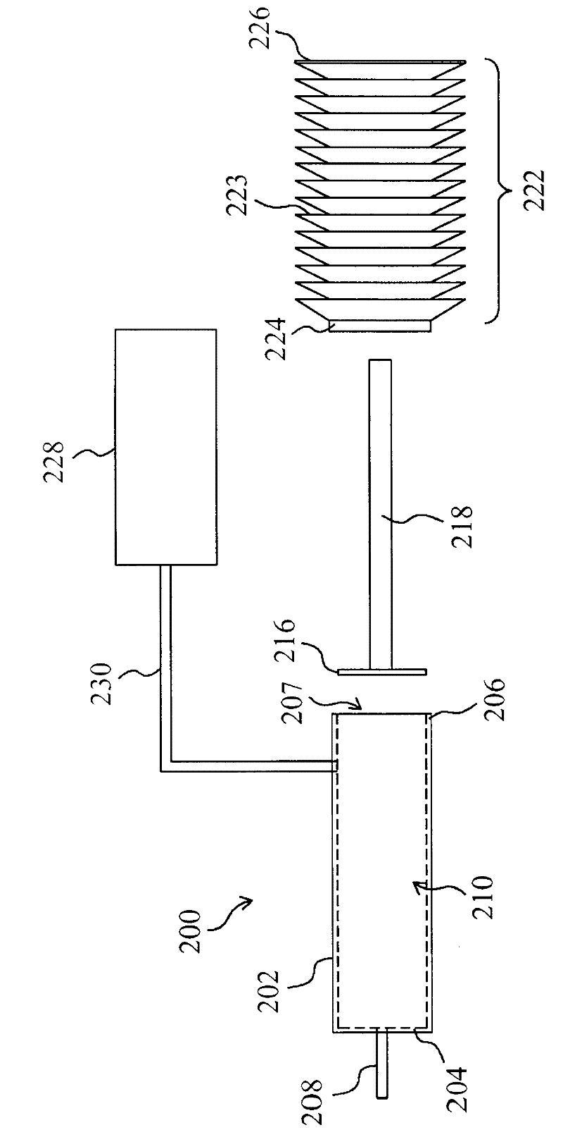
[0075] see now figure 2 with image 3 , figure 2 is a schematic diagram of the first embodiment of the extraction device of the present invention, image 3 yes figure 2 exploded view. As shown in the figure, the extraction device 200 includes a cylinder 202, which includes a hollow chamber 210 and an opening 208. The hollow chamber 210 has an opening 207 at the end 206 of the cylinder 202, and the opening 208 is located at the front end of the cylinder 202. 204 communicates with the hollow chamber 210, a piston 216 is located in the hollow chamber 210, its edge is in contact with the wall of the hollow chamber 210, and the hollow chamber 210 is divided into two regions 212 and 214, and the region 212 is between the piston 216 and the wall of the hollow chamber 210. Between the front ends 204 of the barrel 202, the opening 208 communicates with the out...


PUM


Abstract

The invention relates to an extracting device which comprises a cylinder body, a piston, a pull rod, a buffer matter supply unit and a buffer unit, wherein the cylinder body comprises a hollow cavity which is provided with a first opening at the tail end of the cylinder body and a second opening that is positioned at the front end of the cylinder body and is communicated with the hollow cavity; the piston is positioned into the hollow cavity, the edge of the piston contacts with the wall of the hollow cavity and divides the hollow cavity into a first region and a second region, the first region is positioned between the piston and the front end of the cylinder body, the second region is positioned between the piston and the first opening; the pull rod is connected to the piston and moves the piston; the buffer matter supply unit provides a buffer matter to the second region so as to inhibit impurities from entering the first region; the buffer unit enables the second region to form a closed space and to collect the buffer matter; when the piston moves towards the tail end of the cylinder body, a material is extracted to the first region through the second opening, and the buffer matter is discharged into the buffer unit.

Description

technical field [0001] The present invention relates to an extracting device and method, in particular to an extracting device and method for isolating impurities. Background technique [0002] figure 1 It is a schematic diagram of a known extraction device. As shown in the figure, the known extraction device 100 includes a cylinder 110, which includes a hollow chamber 150, and an opening 140 is located at the front end 112 of the cylinder 110 to communicate with the hollow chamber 150. A piston 120 is located in the hollow chamber 150, and a pull rod 130 is connected to the piston 120 so that the piston 120 moves in the hollow chamber 150. When the piston 120 moves toward the end 114 of the barrel 110, the substance to be extracted is drawn through the opening 140. Aspirated into the hollow chamber 150 , when the piston 120 moves toward the front end 112 of the barrel 110 , the extracted substance in the hollow chamber 150 is discharged through the opening 140 . However, ...

Claims


Application Information

Patent Timeline
Patent Type & Authority Patents(China)
IPC IPC(8): F04B37/18F04B33/00F04B39/00F04B35/01F04B53/14
Inventor 蔡依蒨陈政宏汪瑞民
Owner TAIWAN MAGNETIC INNOVATION TECH
Why Eureka
Try Eureka