Method for identifying pipeline leakage
An identification method and pipeline leakage technology, applied in the field of pipeline leakage detection, can solve the problems of leakage signal, leakage identification accuracy, leakage identification performance degradation, etc., and achieve the effect of improving the signal-to-noise ratio and eliminating noise interference.
Active Publication Date: 2009-12-02
中瓴埃斯科(重庆)环保产业有限公司
View PDF2 Cites 22 Cited by
- Summary
- Abstract
- Description
- Claims
- Application Information
AI Technical Summary
Problems solved by technology
Aiming at the influence of fixed non-leakage sound sources inside and outside the pipe on leak detection, Ai et al. combined the linear predictive coding cepstral coefficient (LPCC) and hidden Markov model (HMM) of the leak sound signal, and Toshitaka and Akira proposed to use the power spectral density of the leak signal , destruction factor based on AR model, etc. are used as the characteristics of the leakage sound signal, combined with the support vector machine (SVM) to distinguish whether the relevant components in the sensing signal come from leakage or various non
Method used
View moreImage
Smart ImageViewing Examples
Examples
 PUM
 Abstract
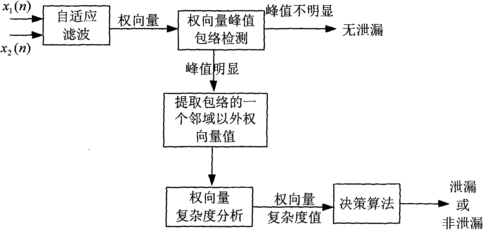
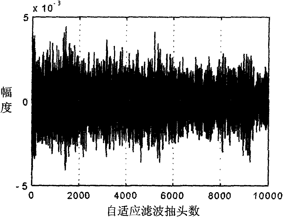
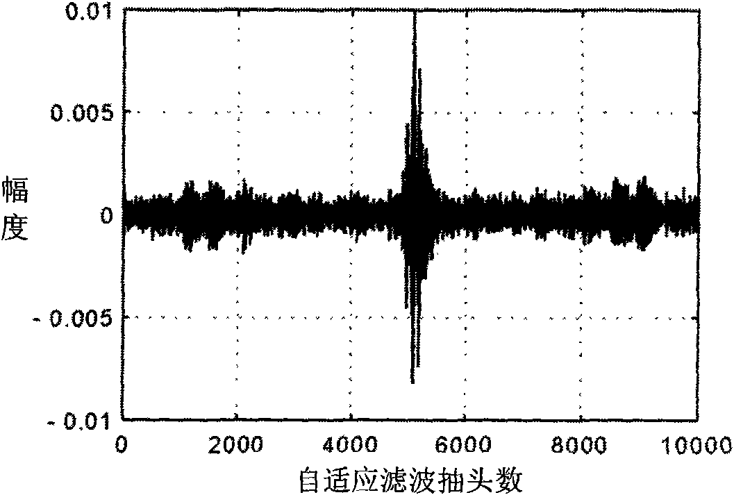
The invention discloses a method for identifying pipeline leakage, which comprises the following steps: aiming at two observation signals of adjacent sensors, using the signals as an input signal and a reference signal of a self-adapting filter respectively, and extracting a weight vector of the filter during convergence, wherein the weight vector is the optimal estimation of the correlation functions of the two observation signals; judging that a pipeline probably leaks when the weight vector of the filter during the convergence has a peak value, otherwise judging that the pipeline has no leakage; and when the judgment result is that the pipeline probably leaks, calculating the weight vector complexity value of the part beyond one neighborhood of the envelope peak value of the weight vector, and inputting the weight vector complexity value into a decision algorithm to finally determine whether the pipeline leaks really. The method has the following technical advantages: not only the noise-signal ratio of signals is improved, but also the correlated characteristics about leakage signals shared in the two signals are highlighted, and the decision algorithm is adopted to perform quantitative analysis on the complexity of the self-adapting filtering weight vector, eliminate noise interference and identify whether a signal source is a real signal source having the leakage.
Description
technical field [0001] The invention relates to a pipeline leakage detection technology, in particular to a pipeline leakage identification method. Background technique [0002] Timely and correct detection of pipeline leakage is the premise of leakage location and the first step of engineering leakage control. [0003] Early engineering leak detection personnel judged whether the water supply pipeline leaked by listening to the sound produced by the leak. This method of identifying leaks that relies on the experience and knowledge of engineers has large subjective factors, low efficiency, and easy missed detection. With the development of technology, the detection methods currently used mainly include: continuous flow detection method, minimum night flow and pipeline pressure signal wavelet analysis, etc. There are shortcomings such as time-consuming detection, limited types of detection pipelines, and the detection area is greatly affected by the ground environment, which...
Claims
Login to View More Application Information
Patent Timeline
 IPC IPC(8): F17D5/06G06N3/02
Inventor 杨进文玉梅李平
Owner 中瓴埃斯科(重庆)环保产业有限公司
Features
- R&D
- Intellectual Property
- Life Sciences
- Materials
- Tech Scout
- Unparalleled Data Quality
- Higher Quality Content
- 60% Fewer Hallucinations
Learn More Browse by: Latest US Patents, China's latest patents, Technical Efficacy Thesaurus, Application Domain, Technology Topic, Popular Technical Reports.
© 2025 PatSnap. All rights reserved.Legal|Privacy policy|Modern Slavery Act Transparency Statement|Sitemap|About US| Contact US: help@patsnap.com


