Coloring and curing mechanism of optical fiber coloring machine

An optical fiber and curing furnace technology, applied in the direction of fiber mechanical structure, etc., can solve the problems of wasting nitrogen, experts are handicapped, waste, etc., and achieve the effect of improving coloring speed, ensuring processing efficiency, and saving nitrogen.

Active Publication Date: 2009-12-02
YANGTZE ZHONGLI OPTICAL FIBER & CABLE (JIANGSU) CO LTD +1
View PDF0 Cites 13 Cited by
  • Summary
  • Abstract
  • Description
  • Claims
  • Application Information

AI Technical Summary

Problems solved by technology

However, this disposal method has an alternative problem of taking care of one thing and losing another. The so-called focus on this, that is, the processing efficiency can be improved, and the so-called loss of the other, that is, because the amount of nitrogen entering the curing furnace is also increased at the same time, it will cause serious problems. waste, which ultimately increases the cost of fiber processing
[0004] In view of the above, it is necessary to find a reasonable balance between not affecting the nitrogen supply required by the ink tank and not causing the waste of nitrogen in the curing furnace. For this reason, the applicant has carried out a large number of expert consultations and literature searches. Obtaining technical inspiration that can be used as a reference, the result is: technical information with no expert hands and uninspiring technical information in the literature

Method used


Image

  • Coloring and curing mechanism of optical fiber coloring machine

Examples


Embodiment

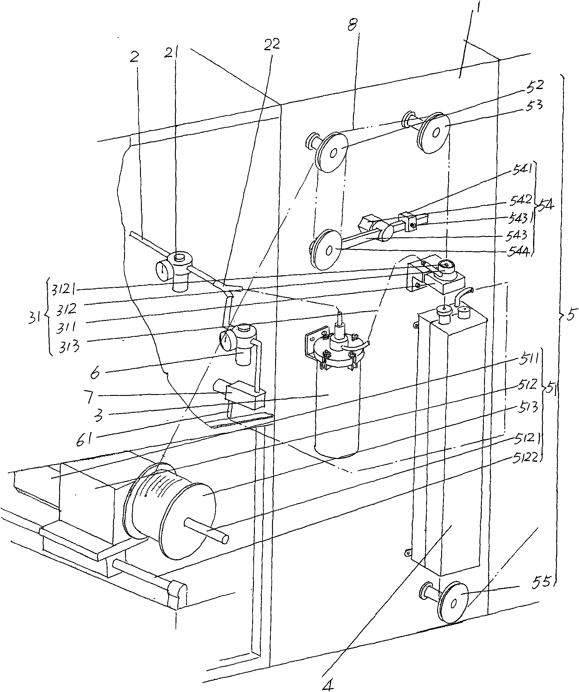
[0019] Please refer to the accompanying drawings, which shows a frame box 1 of an optical fiber coloring machine. The coloring and curing mechanism of the present invention uses the frame box 1 as a carrier, that is, is installed on the frame box 1 . The structure of the preferred coloring and curing mechanism is as follows: one end is connected with the nitrogen source and the other end is connected with the ink tank 3 and the curing furnace 4. The nitrogen inlet pipe 2 is laid on the frame box body 1, as shown in the accompanying drawings, in There is a first pressure regulating valve 21 connected to the pipeline of the nitrogen gas inlet pipe 2, and the first pressure regulating valve 21 can also be called a flow regulating valve (hereinafter the same). As a technical point of the present invention, a three-way interface 22 is fitted on the pipeline at one end of the gas outlet of the nitrogen gas inlet pipe 2 (also can be called the gas outlet side), and one of the interfac...


PUM


Abstract

The invention discloses a coloring and curing mechanism of an optical fiber coloring machine and belongs to the technical field of optical cable processing devices. The optical fiber coloring machine comprises a machine frame box body, and the coloring and curing mechanism comprises a nitrogen inlet pipe provided with a first pressure regulating valve, a printing ink tank, a curing oven and an optical fiber guide device, wherein the printing ink tank and the curing oven are arranged on the machine frame box body; the nitrogen inlet pipe is provided with a three-way connector which arranged in the nitrogen inlet pipe at a position on the air outlet side of the first pressure regulating valve and is connected with the pipes of the printing ink tank and the curing oven respectively; and a second pressure regulating valve is arranged on the pipe connecting the three-way connector and the curing oven. The coloring and curing mechanism of the optical fiber coloring machine has the advantages of increasing nitrogen volume acquired by the printing ink tank, preventing excess nitrogen flow in the curing oven, improving the coloring speed, guaranteeing processing efficiency, saving nitrogen and protecting environment.

Description

technical field [0001] The invention belongs to the technical field of optical cable processing devices, and in particular relates to a coloring and curing mechanism of an optical fiber coloring machine. Background technique [0002] As is well known in the industry, in order to facilitate the identification of optical fibers, it is necessary to smear ink on the outside of the optical fibers, that is, to color the optical fibers, so that each of the several optical fibers in the same optical cable has a corresponding color, which is conducive to improving the laying or maintenance. construction efficiency in the process. In view of this, optical fiber manufacturers including the applicant are almost without exception equipped with optical fiber coloring machines. Although there are imported and domestic optical fiber coloring machines, their structures are roughly the same. At present, the optical fiber coloring machine commonly used by my country's optical fiber production...

Claims


Application Information

Patent Timeline
Patent Type & Authority Applications(China)
IPC IPC(8): G02B6/44
Inventor 衡永革
Owner YANGTZE ZHONGLI OPTICAL FIBER & CABLE (JIANGSU) CO LTD
Why Eureka
Try Eureka