Air nozzle assembly having a joining apparatus

A nozzle and air flow technology, applied in the direction of continuous winding spinning machine, spinning machine, open-end spinning machine, etc., can solve the problem of very strict manufacturing process requirements.

Active Publication Date: 2009-12-09
SAURER GERMANY GMBH & CO KG
View PDF1 Cites 9 Cited by
  • Summary
  • Abstract
  • Description
  • Claims
  • Application Information

AI Technical Summary

Benefits of technology

The technical effect of this patented design described in the current state-of-art involves improving the efficiency and cost savings associated with producing high quality fibers without requiring expensive equipment. By utilizing compressors instead of traditional methods like fans, the production machine does away with bulky components and requires less maintenance compared to older designs. Additionally, the use of separate sources of compressor gas allows for easier handling of the compression system while maintaining efficient operation. Overall, these improvements improve the performance and durability of the resulting fibers produced.

Problems solved by technology

This patented describes a problem where it can be difficult if there were any breaks down on either side of this machine because some parts could get damaged while other components continue working properly.

Method used


Image

  • Air nozzle assembly having a joining apparatus
  • Air nozzle assembly having a joining apparatus
  • Air nozzle assembly having a joining apparatus

Examples


Embodiment Construction

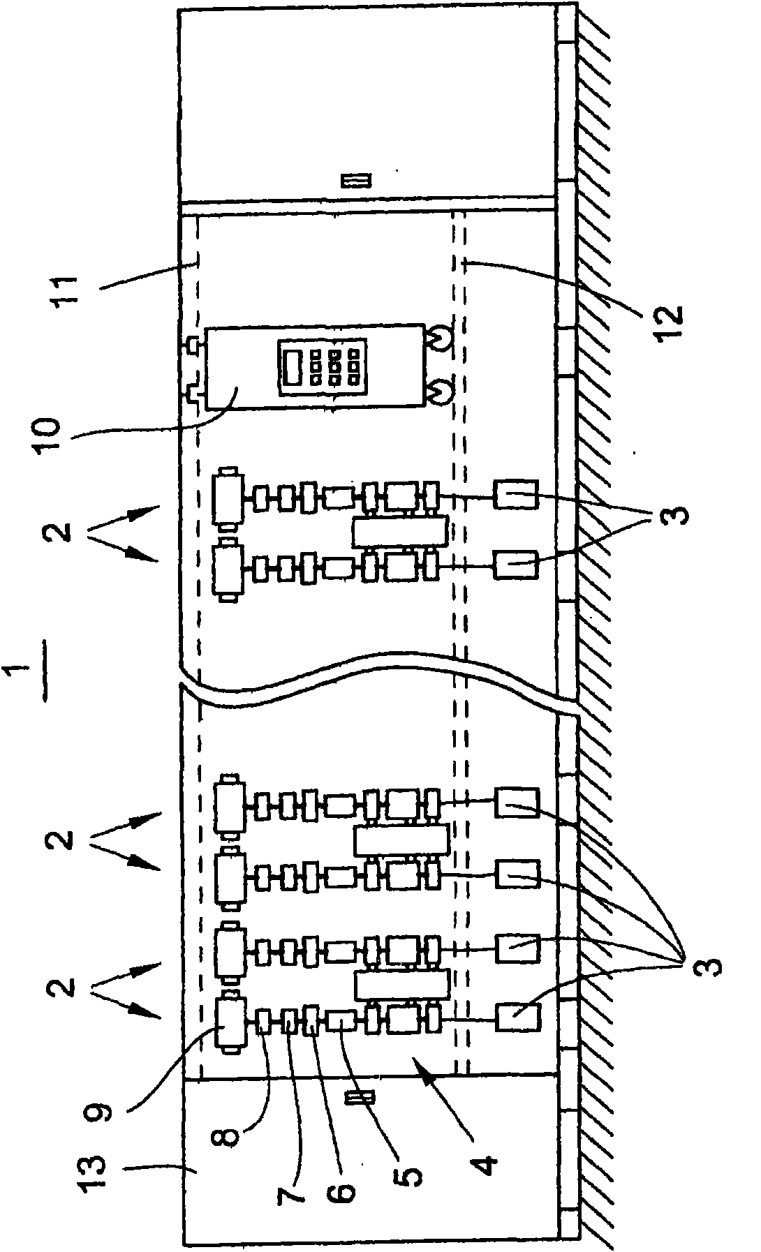
[0020] figure 1 The air spinning machine 1 shown in front view in FIG. 2 has a plurality of work stations 2 arranged next to each other and a drive unit 13 at at least one end of the air spinning machine.

[0021] Each spinning station 2 of an air spinning machine has, for example, a sliver source for a spinning cylinder 3, a drafting device 4, an air spinning device 5, a yarn take-off device 6, a yarn clearer 7 and a yarn traverse device 8. The yarn traversing device 8 is responsible for winding the yarn produced in the air spinning device 5 onto the winding bobbin 9 in a manner that the layers cross each other. The cross-wound bobbin 9 is held in the creel and driven in rotation by the bobbin drive.

[0022] figure 1 Also shown, the automatically working service unit 10 Serving the spinning stations 2 of the air spinning machine 1 , the service unit 10 is guided on guide rails 11 , 12 and can be moved along these spinning stations 2 .

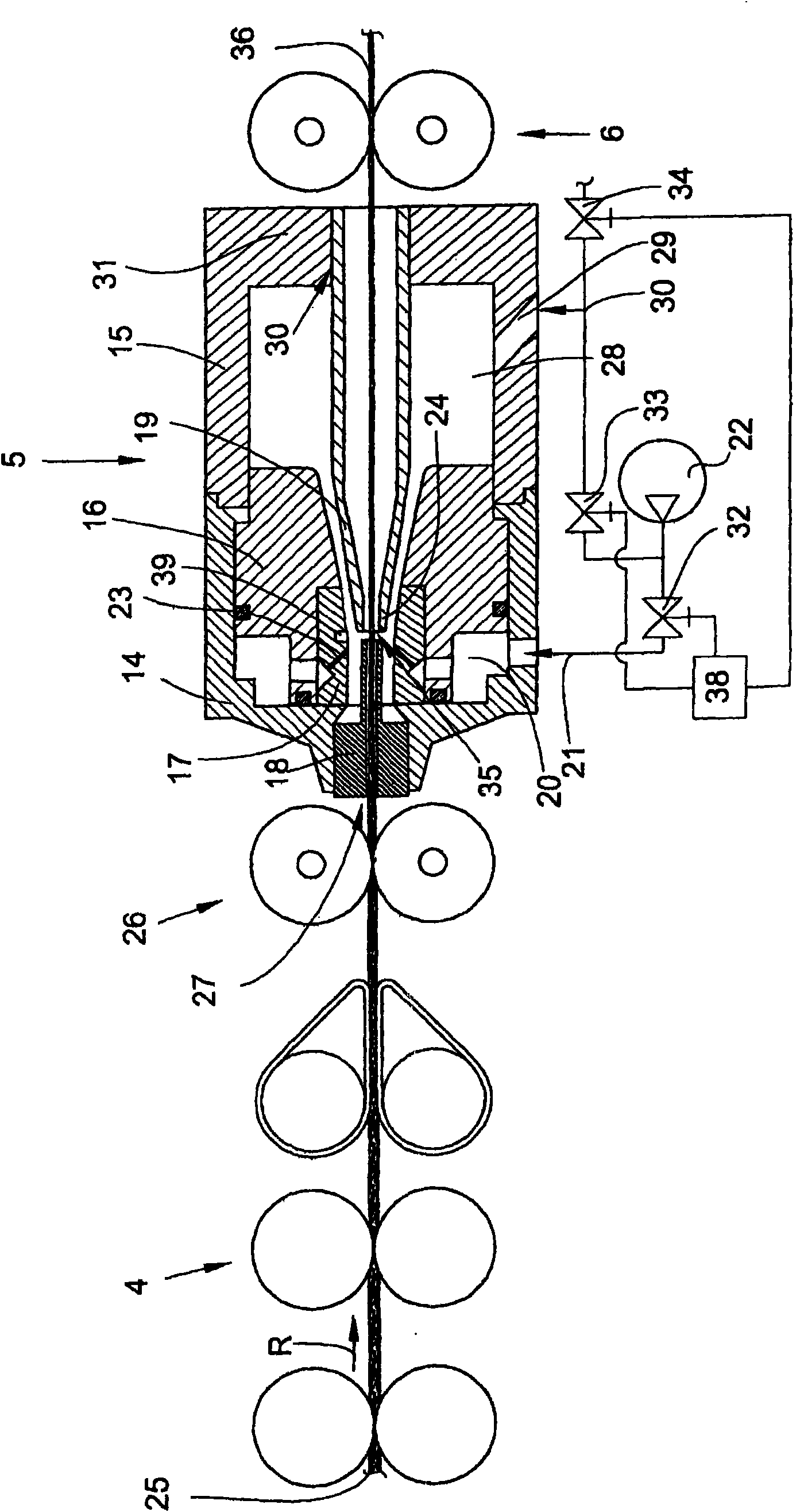
[0023] figure 2 Shown schemati...


PUM


Abstract

The present invention relates to a spinning apparatus (5) for producing a thread (36) by means of a circulating air flow, wherein the spinning apparatus (5) has a hollow spinning cone (19) which is arranged in a spinning housing (14, 15) and, in order to generate the circulating air flow, a nozzle block (17) which can be loaded with compressed air, wherein the spinning housing (14, 15) has an expansion chamber (28) which is provided with at least one waste air channel (29), wherein a compressed air source (22) can be connected to the waste air channel (29) for the joining operation, while the nozzle block can be separated from the compressed air supply, as a result of which an air flow which runs along the spinning cone (19) in the direction of the sliver guide (18) is generated in the spinning housing (14, 15), with the result that a suction effect is produced at the inlet opening (35) of the spinning cone (19), by way of which suction effect a thread (36) can be transported through the spinning cone (19) counter to the spinning direction.

Description


Claims


Application Information

Patent Timeline
Owner SAURER GERMANY GMBH & CO KG
Why Eureka
Try Eureka