Method for determining a functional state of a piezoelectric injector of an internal combustion engine

A technology of piezoelectric injectors and internal combustion engines, which is applied to parts of piezoelectric devices or electrostrictive devices, fuel injection devices, machines/engines, etc., can solve problems such as the influence of electrical characteristic parameters, and achieve accurate capacitance measurement Effect

Inactive Publication Date: 2012-07-18
CONTINENTAL AUTOMOTIVE GMBH
View PDF4 Cites 0 Cited by
  • Summary
  • Abstract
  • Description
  • Claims
  • Application Information

AI Technical Summary

Problems solved by technology

In addition, the application of energy to the piezoelectric injector itself also leads to an influence on the electrical characteristic parameters

Method used


Image

  • Method for determining a functional state of a piezoelectric injector of an internal combustion engine
  • Method for determining a functional state of a piezoelectric injector of an internal combustion engine
  • Method for determining a functional state of a piezoelectric injector of an internal combustion engine

Examples


Embodiment Construction

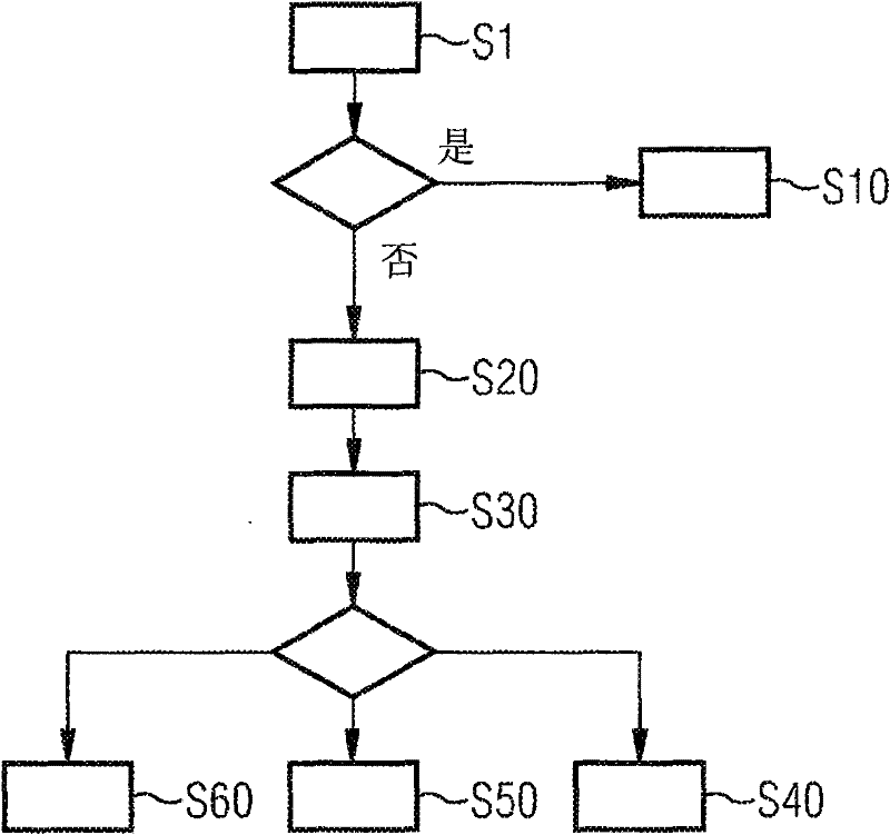
[0023] exist figure 1 A method for detecting an impending failure of a piezo injector is shown in a flow chart.

[0024] In a first step S1 it is checked whether favorable system conditions exist with respect to, for example, the fuel pressure, in order to carry out a capacitive measurement. If this is the case, a capacitance measurement is performed. If a first determined capacitance value is involved in the piezoelectric injector, this first determined capacitance value is stored in step S10 .

[0025] The capacitance value to be compared with the measured capacitance value is calculated in step S20. The calculation is based on a functional equation, which is determined using a mathematical approximation with the aid of the new capacitance value and at least one measured value. The calculated capacitance value is compared with the measured capacitance value in step S30. If the measured capacitance value would be outside the first tolerance range, a signal is sent to the ...


PUM


Abstract

A check is made to determine whether the capacitance value measured at a specific point in time corresponds to a capacitance value of a calculated further capacitance profile or the measured capacitance value is within two tolerance ranges.

Description

technical field [0001] The invention relates to a method for determining the functional state of a piezoelectric injector of an internal combustion engine. Background technique [0002] In recent years, fuel injection systems for operating internal combustion engines have generally been known. In so-called common-rail injection systems, the fuel is delivered via injectors, in particular via piezo injectors, into the corresponding combustion chambers of the internal combustion engine. Here, a high injection pressure is advantageous because, on the one hand, a high specific power of the internal combustion engine and, on the other hand, low pollutant emissions can thereby be achieved. Injection pressures of 1600 to 1800 bar (bar) can be achieved using a high-pressure pump and a pressure accumulator for the fuel. [0003] The fuel quantity determination by the piezo injector is achieved by varying the opening and closing times of its nozzle needle. The electrical and mechani...

Claims


Application Information

Patent Timeline
Patent Type & Authority Patents(China)
IPC IPC(8): H01L41/04
CPCF02D2041/2006H02N2/06F02D41/2096F02D41/221F02D41/20F02M61/16F02D41/02H10N30/80
Inventor R·霍夫曼H·沃尔帕特
Owner CONTINENTAL AUTOMOTIVE GMBH
Why Eureka
Try Eureka