Method, system and device for detecting packet loss rate
A detection method and technology of a detection device are applied in the field of network communication and can solve the problem of inability to detect the LSP packet loss rate and the like
- Summary
- Abstract
- Description
- Claims
- Application Information
AI Technical Summary
Problems solved by technology
Method used
Image
Examples
Embodiment 1
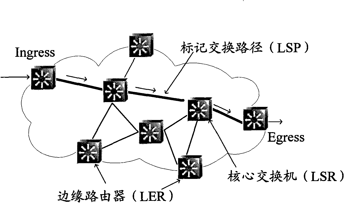
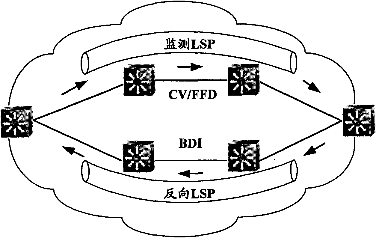
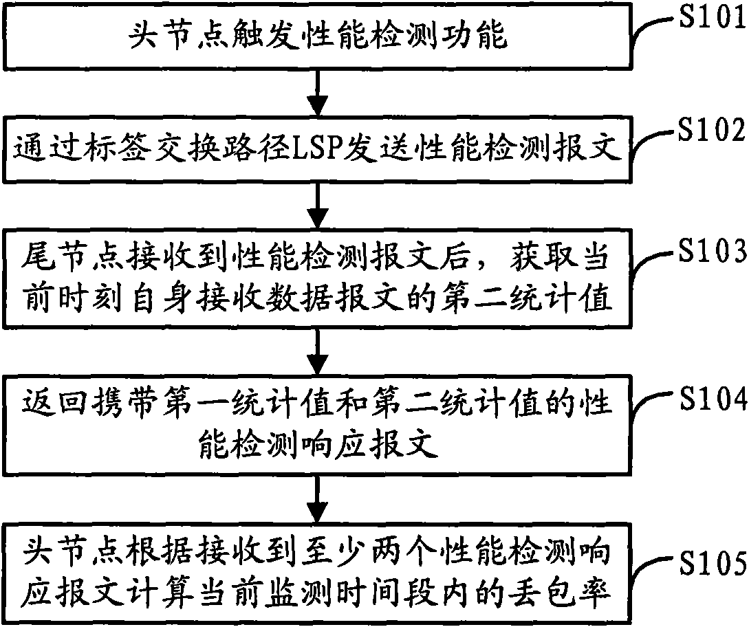
[0092] In the packet loss rate detection method provided by Embodiment 1 of the present invention, the head node sends at least two performance detection messages carrying the real-time statistical value (first statistical value) of the data message sent on the detected LSP to the tail node, and the tail node receives After receiving the data packet, obtain the statistical value of the data packet received by itself from the detected LSP at the receiving time, and return the performance detection response message through the configured reverse LSP. The head node receives at least two performance detection responses according to The statistical value (the first statistical value) of the data message sent by the head node contained in the message and the statistical value (the second statistical value) of the data message received by the tail node, calculate the packet loss rate in the monitoring period, In this way, the detection of the packet loss rate within a certain period o...
Embodiment 2
[0141] The packet loss rate detection method provided by Embodiment 2 of the present invention is different from that in Embodiment 1 in that the tail node calculates the packet loss rate. After the head node sends at least two performance detection messages, the tail node counts the second statistical value of the data message received by itself each time it receives the performance detection message, and the tail node is based on the received at least two performance detection messages. The first statistical value and the corresponding second statistical value contained in the message are calculated to obtain the packet loss rate in the current monitoring time period. Its process is as follows Figure 5 As shown, its execution steps are as follows:
[0142] Step S201: the head node triggers a performance detection function.
[0143] The situations that may be triggered are specifically the same as step S101, and will not be repeated here.
[0144] Step S202: the head node...
PUM
 Abstract
Description
Claims
Application Information
 - R&D
- Intellectual Property
- Life Sciences
- Materials
- Tech Scout
- Unparalleled Data Quality
- Higher Quality Content
- 60% Fewer Hallucinations
Browse by: Latest US Patents, China's latest patents, Technical Efficacy Thesaurus, Application Domain, Technology Topic, Popular Technical Reports.
© 2025 PatSnap. All rights reserved.Legal|Privacy policy|Modern Slavery Act Transparency Statement|Sitemap|About US| Contact US: help@patsnap.com


