
Power transmission device and method of producing the same

A technology of power transmission device and external gear, which is applied in the direction of transmission device, gear transmission device, wind turbine control, etc., to achieve the effect of strong prevention of reverse drive, small backlash and high operation efficiency

Inactive Publication Date: 2009-12-16
SUMITOMO HEAVY IND LTD
View PDF1 Cites 12 Cited by
  • Summary
  • Abstract
  • Description
  • Claims
  • Application Information

AI Technical Summary

Problems solved by technology

[0007] Moreover, because the device in Patent Document 1 uses a gear mechanism to transmit power, it will inevitably produce backlash caused by meshing, so especially when high positioning accuracy is required becomes a problem when the use of

Method used


Image

  • Power transmission device and method of producing the same
  • Power transmission device and method of producing the same
  • Power transmission device and method of producing the same

Examples


Embodiment Construction

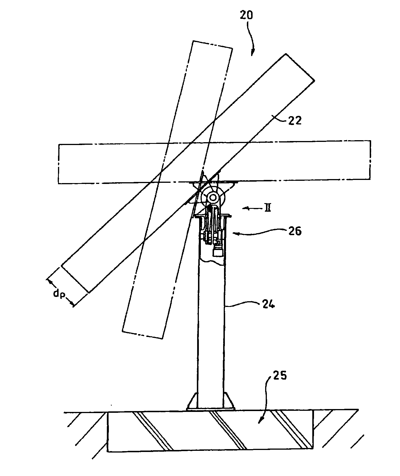
[0033] An example of a driving device of a solar power generation system incorporating a speed reducer which is an example of the power transmission device of the present invention will be described in detail below. figure 1 The outline of the overall structure of this photovoltaic power generation system 20 is shown.

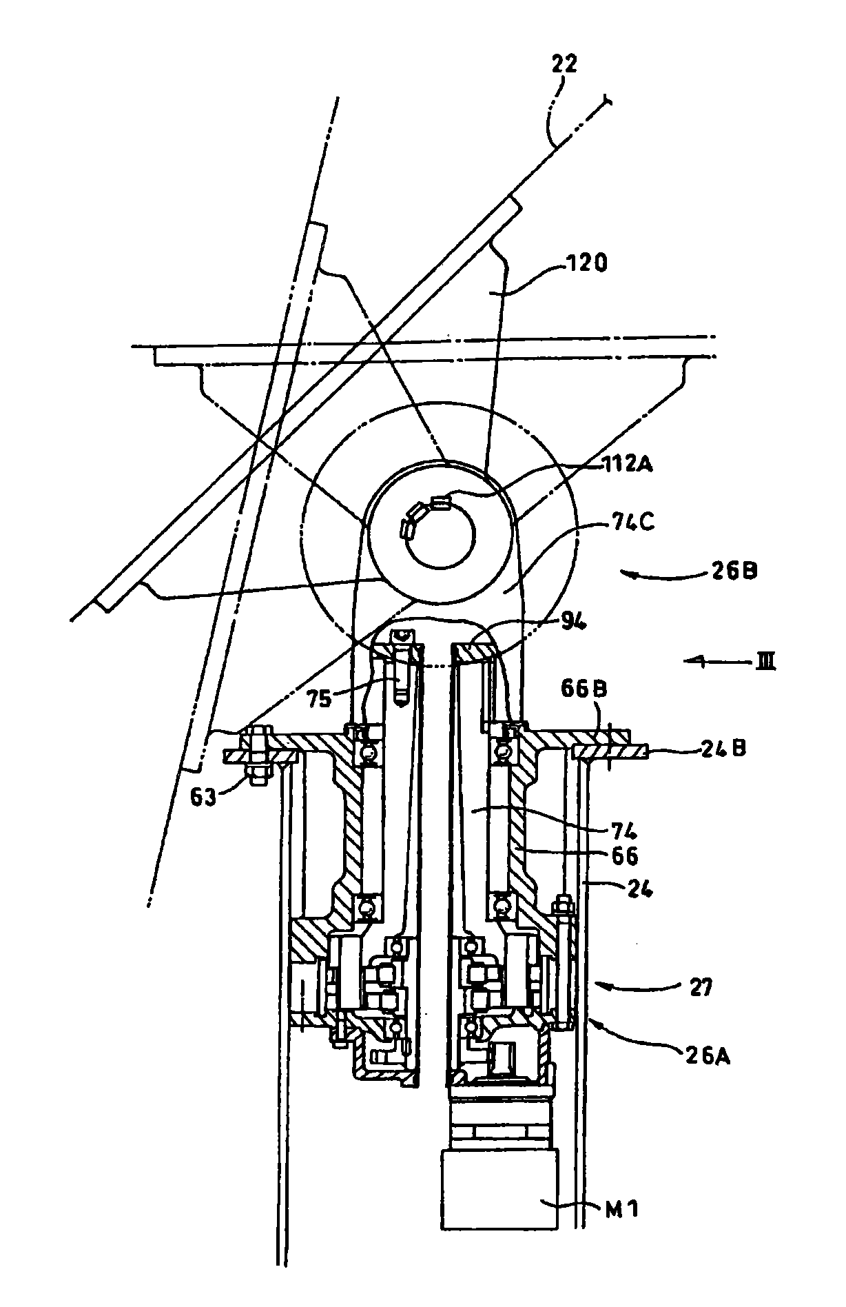
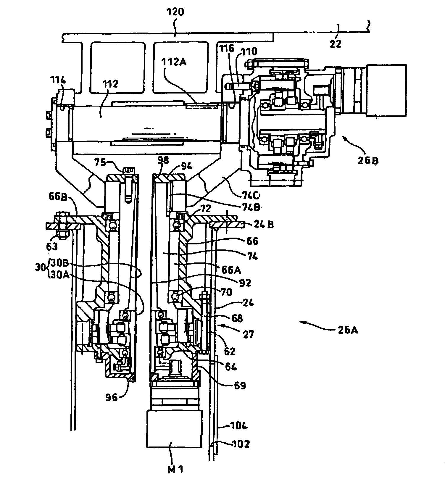
[0034] This solar power generation system 20 has a power generation panel 22 for obtaining electric power from sunlight, and a cylindrical support (support body) 24 for supporting the power generation panel 22 . The cylindrical pillar 24 is erected on an earth platform (base) 25 buried in the ground. The driving device 26 for driving the power generation panel 22 is arranged and housed in the uppermost part of the cylindrical support 24 .

[0035] In order to maximize the power generation efficiency, this embodiment adopts a structure in which sunlight is condensed by a lens not shown in the figure while following the position of the sun, and the light intensi...


PUM


Abstract

A power transmission device having inherently high operation efficiency, having a highly effective reverse drive prevention function, and having very small backlash. The power transmission device has a reduction gear (power transmission device)(26A) having an internally meshing planetary gear mechanism that has an input shaft (44), an eccentric body (46) provided on the input shaft (44), an externally toothed gear (54) eccentrically rocking via the eccentric body (46), and internally toothed gear (60) with which the externally toothed gear (54) internally meshes. The externally toothed gear (54) is assembled to the internally toothed gear (60) in an interference fit.

Description

technical field [0001] The present invention relates to a power transmission device, in particular to a power transmission device with the function of preventing reverse driving and a manufacturing method thereof. Background technique [0002] Depending on the application, the power transmission device may be required to have a back-driving prevention function. Patent Document 1 discloses the following structure of the deceleration mechanism of the drive train: a deceleration mechanism whose starting efficiency is above 40% is adopted, and at a certain position on the power transmission path of the deceleration mechanism, the configuration can be always A friction force imparting device that imparts resistance due to friction to a certain rotating member on the power transmission path. [0003] The feature of this invention is: the difference between static friction and dynamic friction or the difference between starting efficiency and operating efficiency is used to preven...

Claims


Application Information

Patent Timeline
Patent Type & Authority Applications(China)
IPC IPC(8): F16H1/32
CPCY02E10/723F16H2001/325F05B2260/30Y02E10/722F16H1/32F03D7/0204Y10T29/49826Y02E10/72
Inventor 峰岸清次矢野雄二
Owner SUMITOMO HEAVY IND LTD
Learn More