Kicking trainer

A technology of training equipment and fitness equipment, applied in the field of kicking training equipment, can solve the problems of low intensity and few fitness equipment, etc.

Inactive Publication Date: 2009-12-23
李清水
View PDF0 Cites 6 Cited by
  • Summary
  • Abstract
  • Description
  • Claims
  • Application Information

AI Technical Summary

Problems solved by technology

[0002] At present, fitness equipment is widely used in public places. Most fitness equipment is designed for the elderly, with low intensity, and there are few fitness equipment for exercising human leg strength.

Method used


Image

  • Kicking trainer

Examples


Embodiment Construction

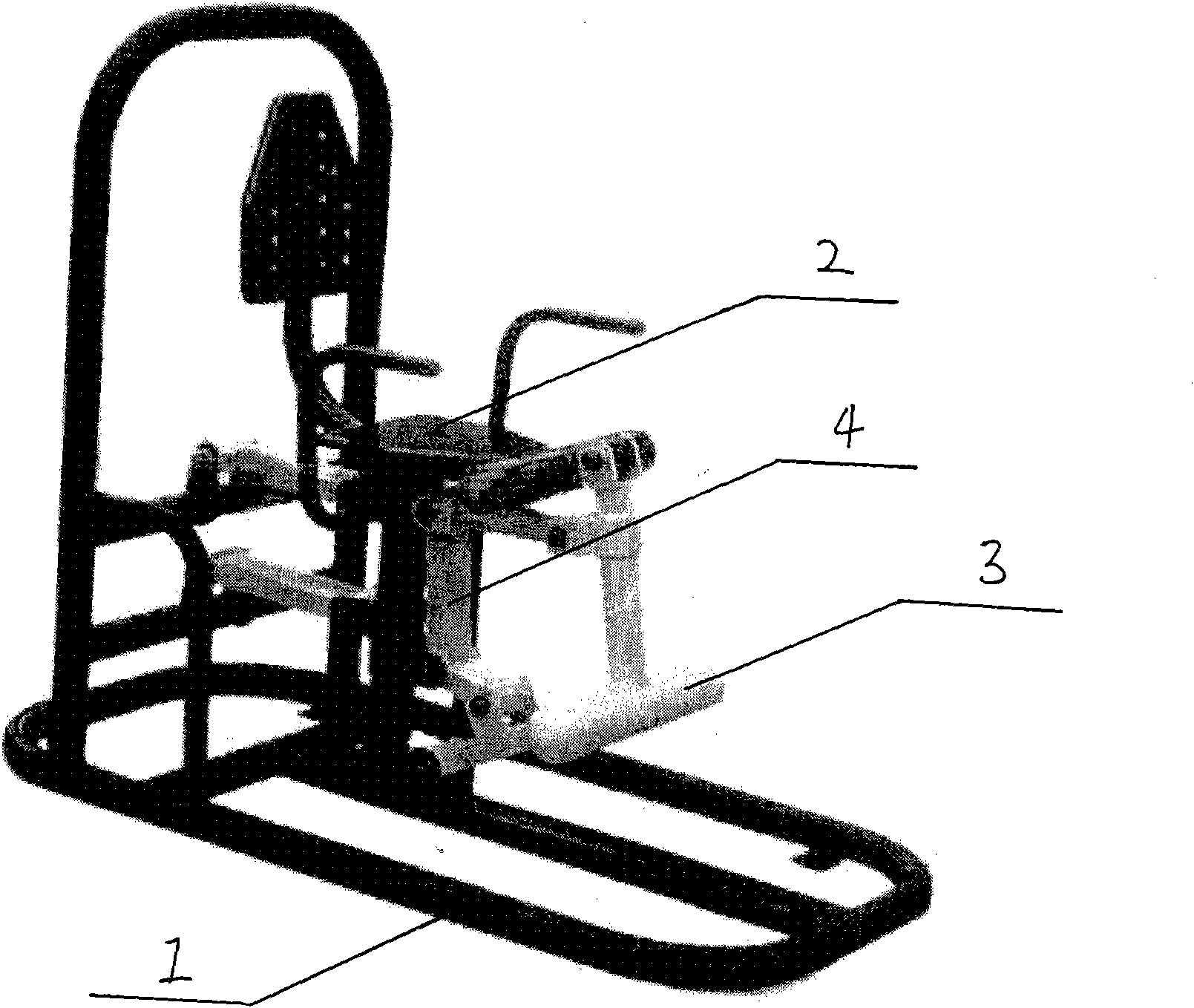
[0008] Such as figure 1 Shown: 1. base, 2. seat, 3. kick cross bar, 4. movable link.

[0009] A kick trainer is composed of a base 1, a seat 2, a kick bar 3, and a movable link 4. The bottom of the pillar of the seat 2 has a buffer pad, the rear end of the pillar is hinged with the rear bracket of the base 1, and the front end is connected with the movable link. The bar 4 middle parts are hinged, the movable connecting rod 4 upper ends are hinged with the kicking cross bar 3 middle parts, the movable connecting rod 4 lower ends are hinged with the base 1, and the kicking cross bar 3 ends are hinged with the seat 2 front ends.

[0010] The exerciser kicks and lifts the kick cross bar 3, the movable connecting rod 4 moves, and the seat 2 pillars connected with it are lifted up, and the exerciser reaches the purpose of training leg strength by overcoming the resistance produced by self-gravity.


PUM


Abstract

The invention discloses a kicking trainer and belongs to a body-building apparatus. The exerciser consists of a base (1), a chair (2), a kicking transverse rod (3) and a movable connecting rod (4), wherein the bottom of a chair (2) backbone has a cushion pad, while the back end of the backbone is hinged with a back bracket of the base (1) and the front end is hinged with the middle part of the movable connecting rod (4); and the upper end of the movable connecting rod (4) is hinged with the middle part of the kicking transverse rod (3), while the lower end is hinged with the base (1). An exerciser can achieve exercise effect by kicking legs to overcome body weight and lift the kicking transverse rod (3). Moreover, the kicking trainer has simple structure and can train leg strength.

Description

technical field [0001] The invention relates to a body-building apparatus, in particular to a kick trainer for exercising human leg strength. Background technique [0002] At present, fitness equipment is widely used in public places. Most of the fitness equipment is designed for the elderly, with low intensity, and there are few fitness equipment for exercising human leg strength. Contents of the invention [0003] The purpose of the present invention is to make up for the vacancy in the mass fitness equipment market and provide a fitness equipment that can effectively exercise the strength of human legs. [0004] The purpose of the present invention is achieved like this: [0005] A kicking training device is composed of a base, a seat, a kicking bar, and a movable link. The seat has a cushion at the bottom of the pillar, the rear end of the pillar is hinged with the rear bracket of the base, and the front end is hinged with the middle part of the movable link. The upp...

Claims


Application Information

Patent Timeline
Patent Type & Authority Applications(China)
IPC IPC(8): A63B23/04A63B21/068
Inventor 李清水
Owner 李清水
Why Eureka
Try Eureka