
Method for determining paste position of strain gauge of sensor

A technology of strain gauges and sensors, applied in the field of sensors, can solve the problems of complex force on pressure sensors, affecting the accuracy of belt scales, and forward thrust interference, etc., and achieve the effects of low cost, reduced interference, and improved measurement accuracy

Active Publication Date: 2009-12-23
广州粤能电力科技开发有限公司
View PDF0 Cites 18 Cited by
  • Summary
  • Abstract
  • Description
  • Claims
  • Application Information

AI Technical Summary

Problems solved by technology

[0004] In the actual operation of the belt, the force of the pressure sensor on the electronic belt scale is complicated. In addition to the pressure generated by the weight of the loaded material, an additional disturbance force will be generated during the operation of the belt.
Due to the load on the belt, a thrust in the same direction as the forward direction will be generated on the pressure sensor during the forward process. The interference of this thrust will inevitably deform the pressure sensor and output interference signals, thus affecting the accuracy of the belt scale.
[0005] At present, most of the solutions to the interference of the forward thrust caused by the load of the belt are from the perspective of improving the structure of the scale frame, such as using a full suspension scale frame, or installing balls on the top of the sensor, etc. The operation is complicated and costly. high

Method used


Image

  • Method for determining paste position of strain gauge of sensor
  • Method for determining paste position of strain gauge of sensor
  • Method for determining paste position of strain gauge of sensor

Examples


Embodiment Construction

[0022] The following will clearly and completely describe the technical solutions in the embodiments of the present invention with reference to the accompanying drawings in the embodiments of the present invention. Obviously, the described embodiments are only some, not all, embodiments of the present invention. Based on the embodiments of the present invention, all other embodiments obtained by persons of ordinary skill in the art without creative efforts fall within the protection scope of the present invention.

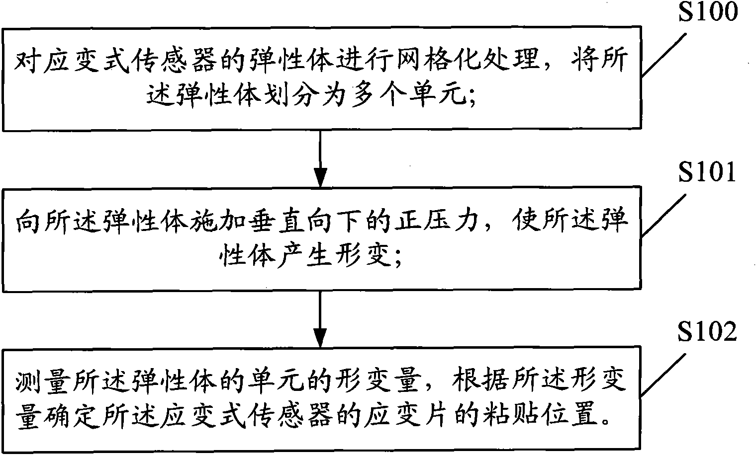
[0023] see figure 1 , is a flow chart of the method for determining the sticking position of the sensor strain gauge provided by the present invention, and the method specifically includes the following steps:

[0024] S100, performing grid processing on the elastic body of the strain gauge sensor, and dividing the elastic body into multiple units;

[0025] S101, applying a vertical downward positive pressure to the elastic body to deform the elastic body;

[002...


PUM


Abstract

The invention discloses a method for determining a paste position of a strain gauge of a sensor. The method comprises the following steps: carrying out gridding treatment on an elastomer of a strain type sensor to divide the elastomer into a plurality of units; applying a vertically downward positive pressure to the elastomer to cause the elastomer to deform; measuring the unit deformation amount of the elastomer; and determining the paste position of the strain gauge of the strain type sensor according to the deformation amount. By adopting the embodiment of the invention, the measurement precision of the strain type sensor can be improved.

Description

technical field [0001] The invention relates to the technical field of sensors, in particular to a method for determining the sticking position of a sensor strain gauge. Background technique [0002] The electronic belt scale is a measuring instrument widely used in industrial production to measure the weight of materials. During the dynamic process of belt operation, the belt passes the loaded materials through the weighing section on the scale frame with constant tension and uniform speed. The weighing bracket transmits the weight of the loaded material to the weighing sensor, and the belt running speed is tracked and measured by the speed sensor, and the cumulative weight of the material can be obtained by calculating the integral of the material weight at a certain speed per unit time. [0003] Most of the pressure sensors used on electronic belt scales are strain gauge sensors, the most common one is the S-type double-hole beam pressure sensor, which uses the resistance...

Claims


Application Information

Patent Timeline
Patent Type & Authority Applications(China)
IPC IPC(8): G01L1/20G01G11/04
Inventor 罗嘉陈锐民宋维俏
Owner 广州粤能电力科技开发有限公司
Learn More