Relay fault detecting circuit

A relay fault detection circuit technology, applied in the direction of circuit breaker testing, etc., can solve the problems of circuit or module detection relay, cannot be used normally, cannot detect relay conversion, etc., and achieve the effect of simple circuit design and convenient use

Active Publication Date: 2009-12-23
MIDEA GRP CO LTD
View PDF0 Cites 51 Cited by
  • Summary
  • Abstract
  • Description
  • Claims
  • Application Information

AI Technical Summary

Problems solved by technology

In the process of use, there are generally two kinds of failures in the relay: one is that the relay receives the turn-on signal but cannot execute it, and the relay contacts cannot be closed and remains in the off state; the other is that the relay receives the turn-off signal but cannot execute it. The relay contact sticks and cannot be disconnected, and remains open all the time
For the first type of fault, the consequence is that the load cannot start to work and cannot be used normally, but it will not bring danger; while the second type of fault will cause the load to continue to perform uncontrolled work, such as the heater continues to heat without stopping, etc. Often lead to major accidents or even catastrophic events
[0003] At present, there is no special circuit or module designed to detect the fault state of the relay in the load circuit using the relay, so in actual use, the controller cannot effectively identify the state of the relay and avoid potential safety hazards caused by the fault of the relay
For the performance detection of the relay, the manufacturer generally adopts the method of connecting the relay, the power supply, and the indicator light in series to detect the state of the indicator light when the relay is turned on. This detection circuit can only detect whether the relay is in the turned-on state to make the circuit conduct , it cannot detect whether the relay can normally switch between the on and off states, and this detection circuit is not suitable for real-time fault detection of the relay on specific products

Method used


Image

  • Relay fault detecting circuit
  • Relay fault detecting circuit
  • Relay fault detecting circuit

Examples


Embodiment Construction

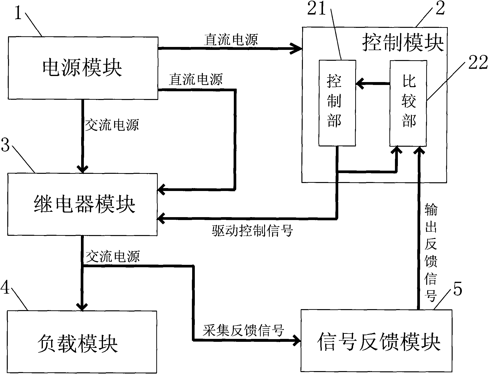
[0015] Such as figure 1 As shown, the fault detection circuit of the relay in this embodiment includes: a power module 1, a control module 2, a relay module 3, a load module 4 and a signal feedback module 5, wherein the load module 4 and the signal feedback module 5 are connected in parallel; the power module 1 is responsible for Provide low-voltage DC power supply to the control module 2 and relay module 3, responsible for providing high-voltage AC power supply to the load module 4 and signal feedback module 5, and the relay module 3 controls the on and off of the AC power supply; the control module 2 includes a control unit 21 and The comparison part 22, the output end of the control part 21 is connected to the relay module 3; the input end of the comparison part 22 is connected to the output end of the signal feedback module 5 and the control part 21; The control unit 21 is responsible for outputting the drive control signal to the relay module 3 and the comparison unit 22,...


PUM


Abstract

The invention discloses a relay fault detecting circuit belonging to the field of relays and comprising a power supply module which can provide a low-voltage DC power supply and a high-voltage AC power supply, a relay module, a control module and a signal feedback module, wherein the control module and the relay module are respectively provided with the low-voltage DC power supply by the power supply module; the control module is connected with the control end of the relay module, and the connecting and disconnecting of the switching end of the relay module is controlled by a driving control signal of the control module; one end of the switching end of the relay module is connected with the output end of the high-voltage AC power supply of the power supply module, and the other end is a load connecting end which is connected with the control module through a signal feedback circuit; and the control module is used for detecting and controlling the fault of the relay module through comparing the driving control signal with a feedback signal. The invention can judge the fault that a relay cannot be connected or disconnected, can simultaneously detect faults of a plurality of relays and has simple circuit design and convenient use.

Description

technical field [0001] The invention relates to the field of relays, in particular to a relay fault detection circuit. Background technique [0002] In the working circuit of the load, the relay control circuit is just an actuator, which turns on or off the relay according to the received control signal, so as to achieve the purpose of controlling the load operation, such as controlling the heating state of the heater and controlling the rotation state of the fan motor etc. In the process of use, there are generally two kinds of failures in the relay: one is that the relay receives the turn-on signal but cannot execute it, and the relay contacts cannot be closed and remains in the off state; the other is that the relay receives the turn-off signal but cannot execute it. The relay contacts are glued and cannot be disconnected, and remain open all the time. For the first type of fault, the consequence is that the load cannot start to work and cannot be used normally, but it ...

Claims


Application Information

Patent Timeline
Patent Type & Authority Applications(China)
IPC IPC(8): G01R31/327
Inventor 房振王健全陈东明常志强
Owner MIDEA GRP CO LTD
Why Eureka
Try Eureka