Quick beamforming method capable of improving array resolution and gain

A resolution and beam technology, applied in the field of array signal processing, can solve the problems of limited performance, poor stability, and high requirements for element consistency, reduce the number of arrays, improve spatial resolution, and simplify the calculation process Effect

A resolution and beam technology, applied in the field of array signal processing, can solve the problems of limited performance, poor stability, and high requirements for element consistency, reduce the number of arrays, improve spatial resolution, and simplify the calculation process Effect

CN101609150AInactive Publication Date: 2009-12-23HARBIN ENG UNIV

Image

  • Quick beamforming method capable of improving array resolution and gain
  • Quick beamforming method capable of improving array resolution and gain
  • Quick beamforming method capable of improving array resolution and gain

Examples


Embodiment Construction

[0020] The present invention is described in more detail below in conjunction with accompanying drawing example:

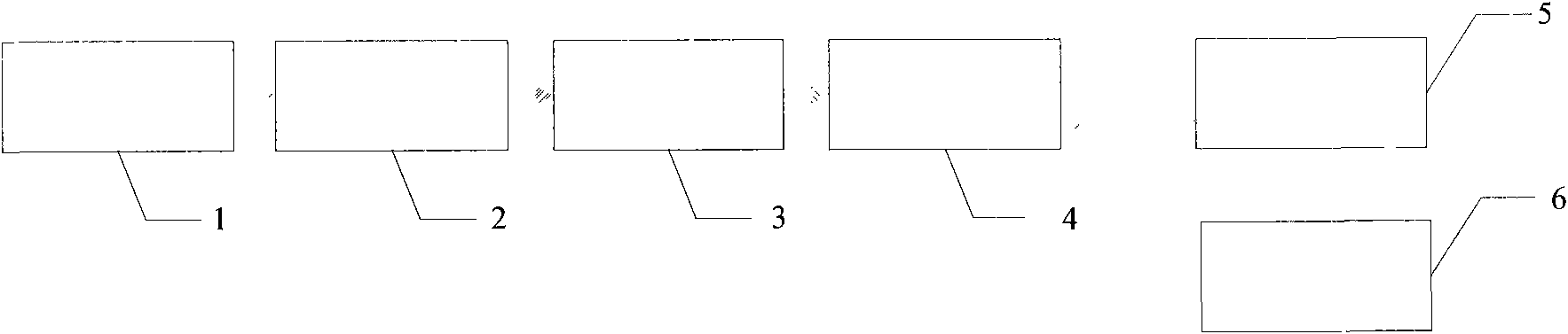
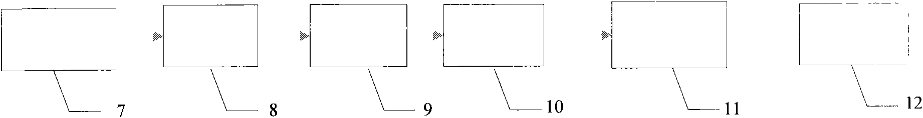
[0021] The transmitting part of the active sonar system (as shown in FIG. 1 ) emits sound waves from the waveform generator 1 through the multi-beam former 2 and the power amplifier 3 . Transceiver switch 4 switches the state of transmission and reception. When the active sonar works in the receiving state, the signal received by the transducer matrix 5 enters the receiver 6 . The present invention utilizes the optimized array 7 as the receiving matrix to effectively reduce the complexity of the receiving system. The signal received by the matrix enters the signal processor 11 through the preamplifier 8 , A / D sampling 9 , filter 10 , and finally enters the terminal for display 12 .

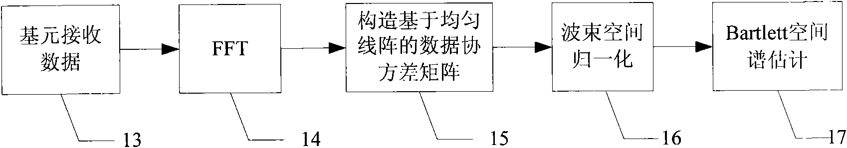
[0022] The present invention proposes a beamforming method for improving beam performance (such as figure 2 ), including performing FFT processing 14 on the received data 13 of th...


PUM


Abstract

The invention provides a quick beamforming method capable of improving array resolution and gain, comprising the following steps: adopting the construction of a minimum redundant array to optimize an M-element uniform linear array into a P-element non-uniform linear array; carrying out FFT processing on primitive data of a P-element array; in a frequency domain, constructing a covariance matrix of data based on the uniform linear array in accordance with the array aperture extension characteristics of fourth-order cumulants; carrying out normalization processing on the beam space and carrying out estimation on a Bartlett spatial spectrum. By adopting the array aperture extension characteristics of the fourth-order cumulants, the invention realizes that the optimized element layout form is employed to obtain high resolution and overcomes the defects of high requirements of the original fourth-order cumulant-based methods on snapshots and great computational complexity to enable the computation process to be simple and easy to operate. When the signal to noise ratio is higher than the supercritical signal to noise ratio, the method of the invention has higher array gain than that of conventional beamforming. The normalization processing of the beam space realizes effective inhibition to background interference. The beamforming method of the invention is simple and easy to operate and is especially suitable for project application.

Description


Claims


Application Information

Patent Timeline
23 Dec 2009
Publication
CN101609150A