Automatic temperature-controlled illuminant indicator

A technology of automatic temperature control and signage, applied in the field of municipal transportation, can solve the problems of limited luminous energy and inconvenience to passers-by

Inactive Publication Date: 2009-12-23
深圳市中庆微科技开发有限公司
View PDF0 Cites 4 Cited by
  • Summary
  • Abstract
  • Description
  • Claims
  • Application Information

AI Technical Summary

Problems solved by technology

However, this passive light-emitting method has limited luminous energy after all. In places with poor light, the human eyes cannot see the information of the

Method used


Image

  • Automatic temperature-controlled illuminant indicator
  • Automatic temperature-controlled illuminant indicator
  • Automatic temperature-controlled illuminant indicator

Examples


Embodiment 1

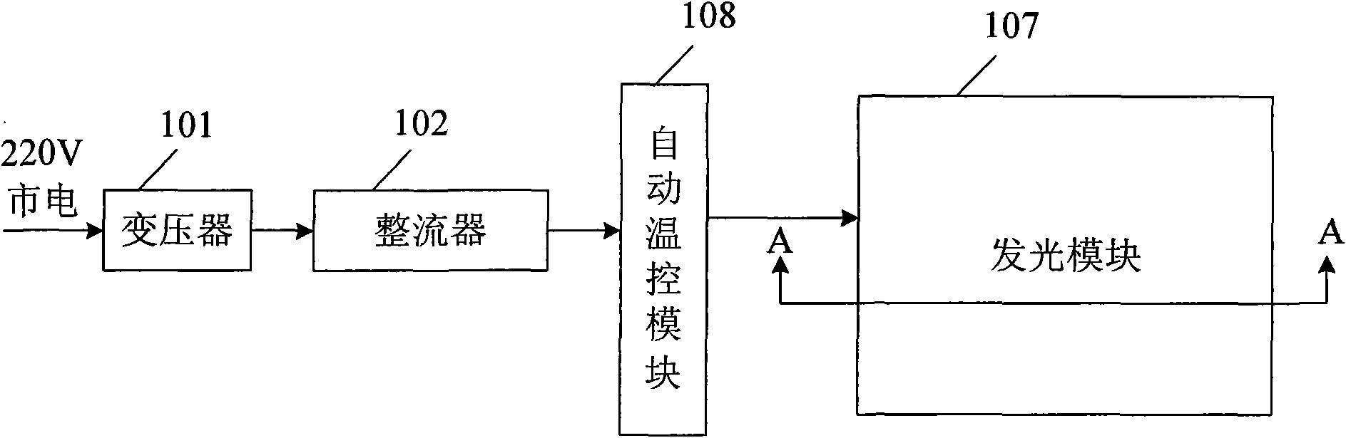
[0031] Such as figure 1 As shown, the present invention provides a road light-emitting sign whose brightness can be automatically adjusted, including: a power supply module, an automatic temperature control module 108 and a light-emitting module 107. The power supply module includes a transformer 101 and a rectifier 102, which are used to provide Constant current power supply. The automatic temperature control module 108 is used to control the brightness of the light emitting module 107 for timely adjustment according to the working environment temperature of the light emitting module.

[0032] The electroluminescent components of the light-emitting module, such as light-emitting diodes, including LEDs and OLEDs, or electroluminescent devices made of other polymer light-emitting materials. It is a temperature-sensitive element. When the temperature is high, the luminous effect and durability will drop sharply, which will affect the reliability and durability of the system; U...

Embodiment 2

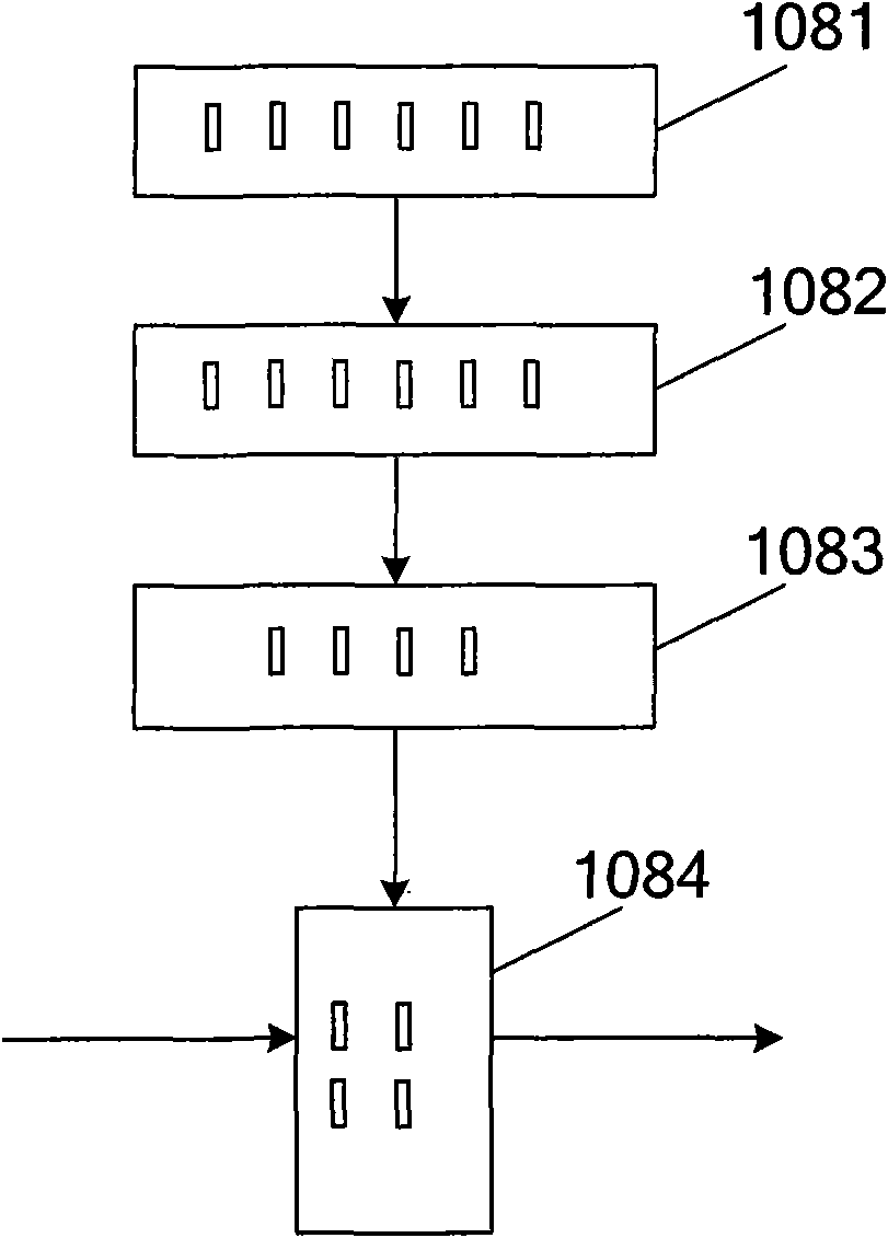
[0039] On the basis of Embodiment 1, this embodiment preferably adopts the following scheme to realize the adjustment function of the automatic temperature control module 108, such as figure 2 As shown, the automatic temperature control module 108 includes a temperature sensing unit 1081, which is arranged inside the light emitting module 107, and is used to monitor the temperature change of the working environment of the light emitting module 107. The temperature analog monitored by the sensing unit 1082 is converted into a digital signal that can be recognized by the system. The control unit 1083 is connected to the analog-to-digital conversion unit 1082, and is used to output different control signals to the execution unit 1084 according to the above digital signal, and the control execution unit 1084 outputs Different brightness data are sent to the light emitting module 107, that is to say, the control unit 1083 outputs a control signal to the execution unit 1084, and the...

Embodiment 3

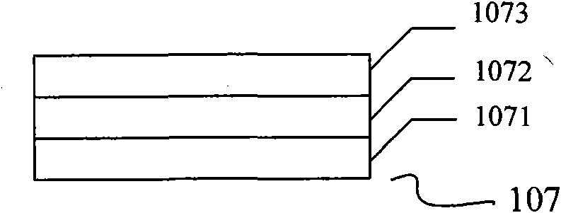
[0042] Such as image 3As shown, the light-emitting module 107 includes a substrate 1071, a light-emitting layer 1072, and an energy storage layer 1073 stacked together in sequence for displaying specific information. 1071 is fixedly connected; for example, in order to simplify the process, the light-emitting layer 1072 and the substrate 1071 can also be integrally formed, and the energy storage layer 1073 is fixedly connected to the light-emitting layer 1072 .

[0043] The material used for the energy storage layer is transparent, for example, it is formed by using water-based acrylic energy storage luminous paint uniformly distributed in resin or plastic.

[0044] Moreover, the shape of the energy storage layer should be consistent with the light emitting layer 1072, that is, it is necessary to form characters or patterns consistent with the light emitting layer 1072, so that when the light emitting layer 1072 emits light, the light can be scattered outward through the energ...


PUM


Abstract

The invention discloses an automatic temperature-controlled illuminant indicator, which comprises: a power supply module, an automatic temperature-controlling module and at least one illuminant module which are interconnected in sequence. An electroluminescent device, especially an LED, belongs to a temperature-sensitive device, and as working in open-air environment, the illuminant indicator board confronts awfully abominable temperature conditions, as a result, the majority of the indictor boards are damaged in relation to overhigh temperature, in the meantime, if the brightness is too strong in high temperature environment, uncomfortable feeling is brought to people; by monitoring environmental temperature of the indicator board in real-time, the invention enables the indicator board to display different brightness in accordance with different temperatures, which not only can meet the visual demand of human eyes, but can also achieve the purposes of saving energy, reducing consumption and prolonging service life of devices.

Description

technical field [0001] The invention relates to the field of municipal transportation, in particular to an automatic temperature-controlled luminous sign. Background technique [0002] Road signs are an important municipal facility, mainly used in municipal engineering, road indication, street beautification and other fields, including but not limited to the following functions: [0003] Warning: A sign that warns vehicles and pedestrians of dangerous locations. [0004] Prohibition: A sign that prohibits or restricts the traffic behavior of vehicles and pedestrians. [0005] Instructions: signs indicating the movement of vehicles and pedestrians. [0006] Wayfinding: A sign that conveys road direction, location, and distance information. [0007] Tourist area: provide signs for the direction and distance of tourist attractions. [0008] Road construction safety: Signs announcing traffic in road construction areas. [0009] Most of the signboards currently used are pass...

Claims


Application Information

Patent Timeline
IPC IPC(8): G09F9/33G09G3/32
Inventor 商松
Owner 深圳市中庆微科技开发有限公司
Why Eureka
Try Eureka