Magnetic fixing device

A fixing device and magnetic force technology, which is applied in the field of magnetic fixing devices, can solve the problems that the magnetic unit does not report to the operation panel, and it is impossible to simply identify the adsorption state or non-adsorption state of multiple magnetic units.

Active Publication Date: 2009-12-23
PASCAL ENG
View PDF1 Cites 16 Cited by
  • Summary
  • Abstract
  • Description
  • Claims
  • Application Information

AI Technical Summary

Problems solved by technology

[0008] However, in the magnetic fixing device of the prior art, there is the following problem: whether the magnetic unit is in the adsorption state or the non-adsorption state does not notify the parts other than the operation panel, so after the mold is fixed or the fixation is released, some operators cannot easily The problem of accurately identifying whether multiple magnetic units are attracted or not

Method used


Image

  • Magnetic fixing device
  • Magnetic fixing device
  • Magnetic fixing device

Examples


Embodiment 1

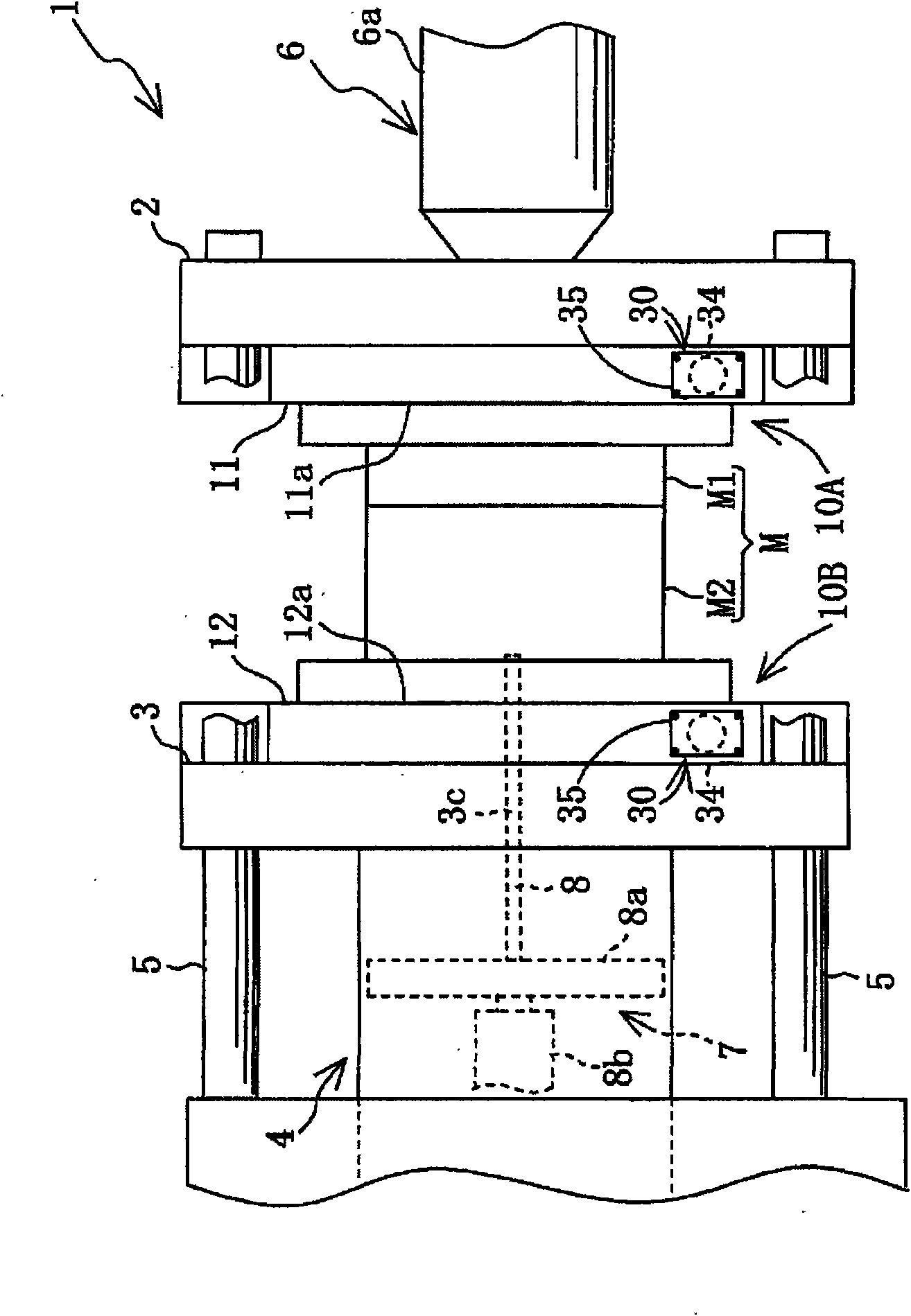
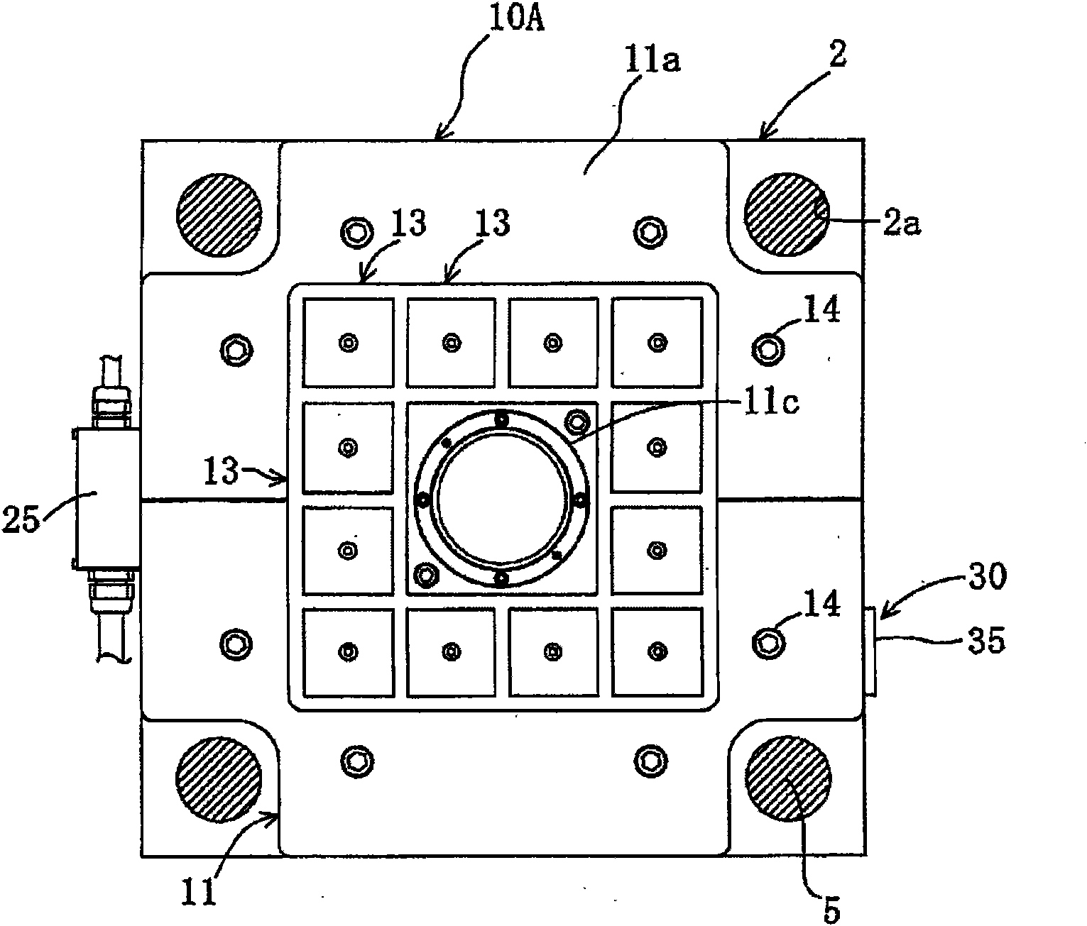
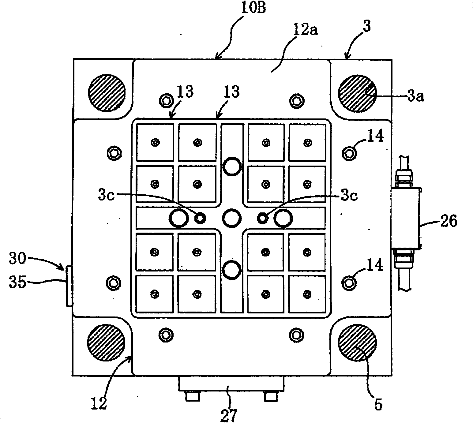
[0063] This embodiment is an example when the present invention is applied to an injection molding machine, so first, the injection molding machine 1 will be described. Such as figure 1 As shown, the injection molding machine 1 includes: a fixed side template 2 and a movable side template 3 facing each other, which are used to fix the mold M (the fixed side mold M1 and the movable side mold M2) as the clamping object; the template driving mechanism 4. It has a hydraulic cylinder (or drive motor), and is used to drive the template 3 close to / away from the template 2, so as to lock or open the mold M; four guide rods 5 guide the support template 3, so that Move freely in the approach / away direction; the injection mechanism 6 has an injection cylinder 6a, and the injection cylinder 6a injects molten synthetic resin into the mold cavity in the mold M in a mold-locked state; and an ejection mechanism 7, which will form The product is released from the mold M2.

[0064] When this ...

Embodiment 2

[0112] Next, the magnetic fastening devices 10A and 10B of the second embodiment will be described. However, the same reference numerals are assigned to the same configurations as in the first embodiment, and description thereof will be omitted. Instead of the actuation state display device 30 described above, an actuation state display device 50 is provided at the same position of the clamping plates 11 , 12 . The operating state display device 50 includes a display lamp 51 and a box member 52 for accommodating the display lamp 51 . The display lamp 51 outputs red light when the magnetic fixing devices 10A, 10B are in the adsorption state, and outputs green light when the magnetic fixing devices 10A, 10B are in the non-adsorption state. An operation control unit for operating and controlling the display lamp 51 is also provided.

Embodiment 3

[0114] Next, the magnetic force type fixing device 10C of the third embodiment will be described. However, the same reference numerals are assigned to the same constituent elements as those in Embodiment 1, and description thereof will be omitted. Such as Figure 18 As shown, the magnetic force type fixing device 10C is mounted and fixed on the platform of a comprehensive processing machine (machining center), for example, and utilizes magnetic force to attract and fix the workpiece pallet (clamping object), and the workpiece pallet is fixed with a Machined workpieces.

[0115]The magnetic fixing device 10C includes: a clamping plate 60 having a fixing surface 60a; a plurality of magnetic units 13 arranged on the clamping plate 60 and generating an adsorption force formed by magnetic force; and operating state display mechanisms 30E-30G , is provided on the front end portion (outer peripheral surface) of the clamping plate 60, and can display a mark indicating whether the pl...


PUM


Abstract

A magnetic fixing device comprises a clamp plate having a fixing surface for fixing a clamping object, and a plurality of magnetic force generation mechanisms. Each magnetic force generation mechanism has a magnetic member facing the fixing surface, a plurality of permanent magnets arranged on the outer circumferential side of the magnetic member, a first alnico magnet arranged on the back side of the magnetic member, and a first coil for switching the polarity of the first alnico magnet. The magnetic force generation mechanism is arranged to be switched between a state where the clamping object is attracted, and a state where the clamp object is not attracted. On the fixing surface or the outer circumferential surface of the clamp plate, an operating state indication mechanism indicatingan index showing whether the plurality of magnetic force generation mechanisms are in the attracting state or non-attracting state is provided.

Description

technical field [0001] The present invention relates to a magnetic force type fixing device embedded in a clamp plate of an injection molding machine, etc., and more particularly to a device configured so that an operator can easily recognize a plurality of magnetic force generating mechanisms that attract and clamp an object in the adsorbed or non-adsorbed state. Background technique [0002] In the injection molding machine of the prior art, the mold (fixed side mold and movable side mold) is fixed on a platen such as a fixed plate or a movable platen, and the movable platen is moved closer to or farther away from the fixed platen by moving and driving. Side formwork for mold clamping and mold opening. With the molds locked, inject molten synthetic resin into the internal cavities of the molds to form the molded product, then open the mold and eject the molded product by the ejector mechanism. [0003] Here, fixing the mold on the die plate of the injection molding machi...

Claims


Application Information

Patent Timeline
Patent Type & Authority Applications(China)
IPC IPC(8): B23Q3/15B29C33/32B29C45/26
CPCB29C45/1742B29C2045/1746
Inventor 木村清二
Owner PASCAL ENG
Why Eureka
Try Eureka