Filter for a fabric dyeing machine

A filter and cloth dyeing machine technology, applied in the filter field, can solve the problems of reducing the efficiency and productivity of the cloth dyeing machine, time-consuming filter cleaning, etc.

Inactive Publication Date: 2009-12-30
FALMER INVESTMENTS LTD
View PDF0 Cites 9 Cited by
  • Summary
  • Abstract
  • Description
  • Claims
  • Application Information

AI Technical Summary

Problems solved by technology

Therefore, filter cleaning is time consuming and reduces the efficiency and productivity of the dyeing machine

Method used


Image

  • Filter for a fabric dyeing machine
  • Filter for a fabric dyeing machine
  • Filter for a fabric dyeing machine

Examples


Embodiment Construction

[0019] The present invention proposes a self-cleaning filter used in a cloth dyeing machine to save or reduce the need for manual filter cleaning.

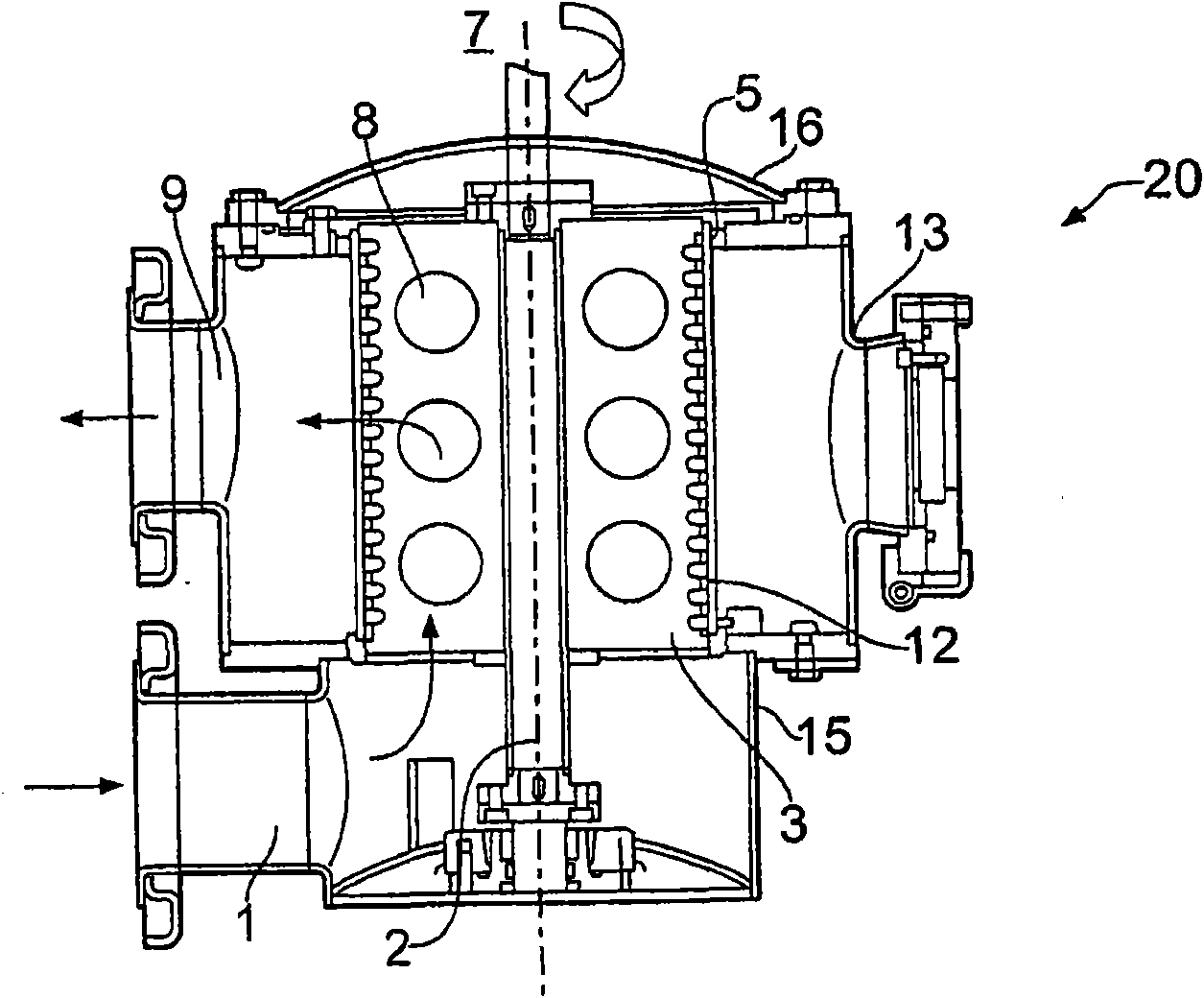
[0020] figure 1 A cutaway side view of a filter according to one embodiment of the invention is shown. The filter 20 comprises a hollow container 15 which accommodates various components which will be described later. The container 15 is generally cylindrical and is provided with a fluid inlet 1 at the lower part of its side wall and a fluid outlet 9 at the upper part of its side wall. The inlet 2 and the outlet 9 are arranged to be connected to the pipes defining the flow path of the dye liquor in the dyeing machine. Thus, the dye liquor from the dyeing machine can enter the inlet 1, pass upwards through the central part of the container 15, and return to the dyeing machine via the outlet 9, as figure 1 indicated by the arrow in .

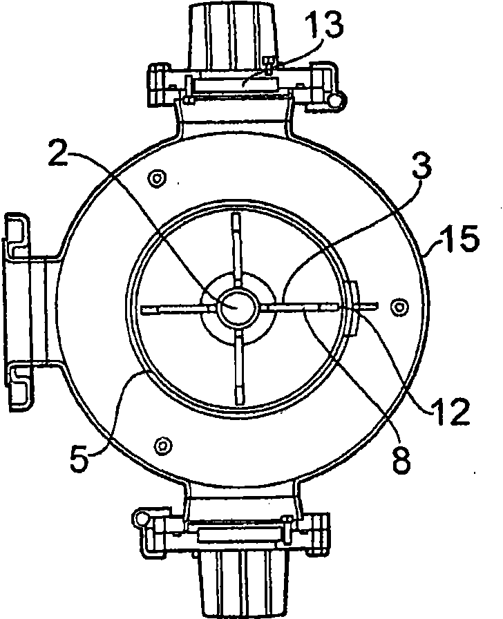
[0021] A rotatable shaft 2 is mounted vertically through the center of the container 15 . Sui...


PUM


Abstract

A filter for a fabric dyeing machine comprises a filter plate (5) configured to be placed across a flow path for dye liquor in a dyeing machine, the plate having perforations for dye liquor to pass through, and at least one blade (3) with a scraping edge (12), the blade movably mounted with respect to the plate such that movement of the blade carries the scraping edge across the perforations in the plate, the action of the scraping edge across the perforations breaking up lint trapped by the plate until the lint is small enough to pass through the perforations. The plate may be tubular, with a plurality of blades mounted radially on a rotatable shaft (2) coaxial with the plate. The plate and the blades may be housed in a vessel (15) having an inlet (1) and an outlet (9) for connection of the filter into the dye liquor flow path of a dyeing machine.

Description

technical field [0001] The invention relates to a filter for a cloth dyeing machine. Background technique [0002] The fabric is usually dyed by circulating it in a dyeing machine filled with a dye liquor. During this dyeing process, thread ends will come off the fabric and accumulate in the dye liquor. There are many narrow fluid channels in the dyeing machine, such as nozzle gaps, which will collect thread ends, and the flow area of ​​​​the channels will be reduced or completely blocked. Mechanical filters are often used to solve this problem. However, while these filters prevent lint from accumulating in the nozzle gap, the accumulation of lint in the filter creates a pressure loss in the fluid circulation, which reduces the exchange of dye liquor between the dye and the fabric. Therefore, the filter must be taken out of the dyeing machine for manual cleaning. Lint attached to the surface of the filter must be removed, which is particularly difficult when removing lon...

Claims


Application Information

Patent Timeline
Patent Type & Authority Applications(China)
IPC IPC(8): B01D29/35B01D29/64D06B23/20
CPCB01D29/03B01D29/35B01D29/035B01D29/62B01D29/6476B01D29/6484
Inventor 徐达明
Owner FALMER INVESTMENTS LTD
Why Eureka
Try Eureka