Shift register circuit with bi-directional transmission mechanism

A shift register and two-way transmission technology, which is applied in static memory, digital memory information, instruments, etc., can solve the problems that cannot be used to provide high picture quality, and achieve the goal of suppressing moiré effect, reducing cost, and extending operating life Effect

Active Publication Date: 2012-02-29
AU OPTRONICS CORP
View PDF4 Cites 0 Cited by
  • Summary
  • Abstract
  • Description
  • Claims
  • Application Information

AI Technical Summary

Problems solved by technology

[0004] In the operation of the shift register circuit 100, the multi-level shift register can only perform unidirectional scanning according to the start pulse signal downlink mode and sequentially output the gate signal of the high voltage level pulse, which is easy to cause the display The moiré effect (Mura effect) of the picture, in other words, the unidirectional scanning operation mode of the existing shift register circuit 100 cannot be used to provide high picture quality

Method used


Image

  • Shift register circuit with bi-directional transmission mechanism
  • Shift register circuit with bi-directional transmission mechanism
  • Shift register circuit with bi-directional transmission mechanism

Examples


Embodiment Construction

[0072] In order to make the present invention more understandable, the specific embodiments of the shift register circuit with a bidirectional transmission mechanism according to the present invention will be described in detail below with reference to the accompanying drawings, but the provided embodiments are not intended to limit the scope of the present invention. range.

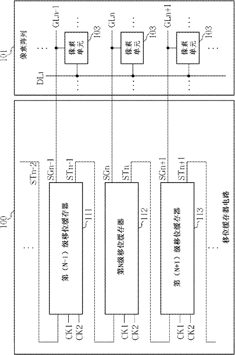
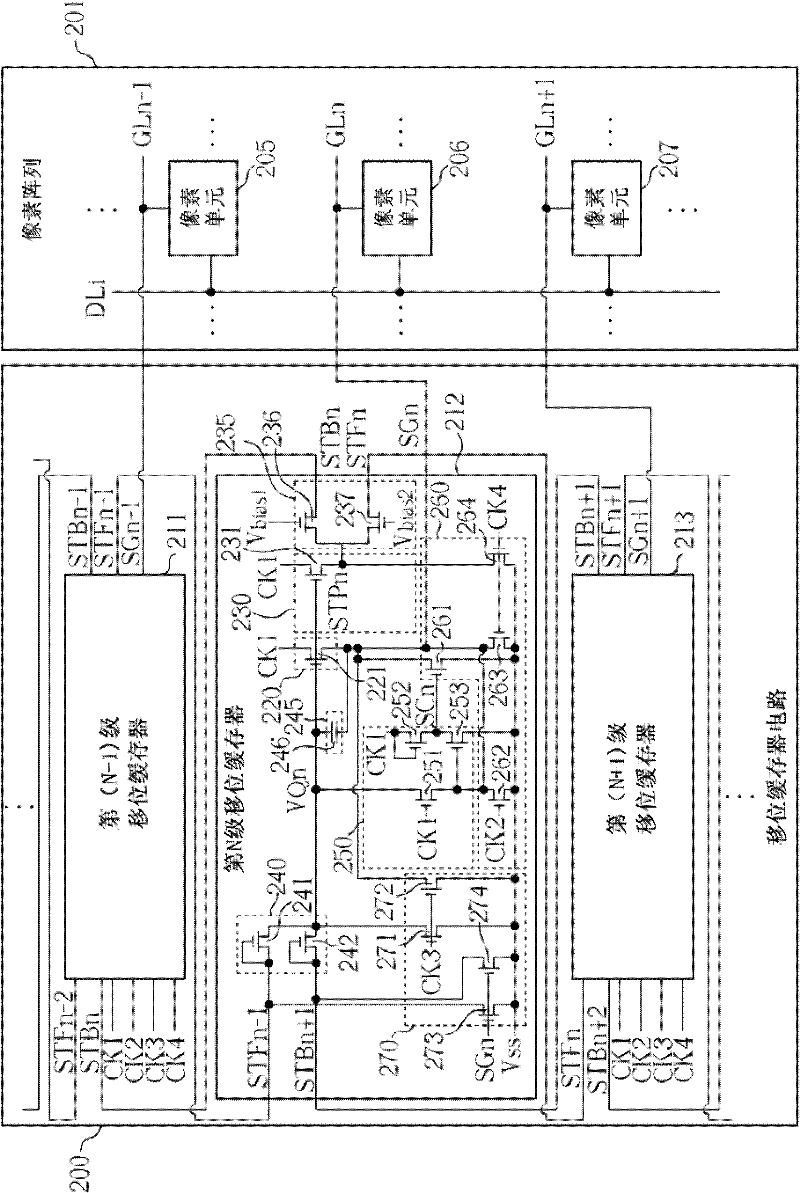
[0073] figure 2 It is a schematic diagram of the shift register circuit 200 according to the first embodiment of the present invention. Such as figure 2 As shown, the shift register circuit 200 includes a multi-stage shift register. For the convenience of illustration, the shift register circuit 200 only shows the N-1th stage shift register 211, the Nth stage shift register 212 and the N+1th stage shift register 213, and N is a positive integer greater than 1 , wherein only the Nth-stage shift register 212 shows the internal functional unit circuit structure, and the rest of the multi-stage shift re...


PUM


Abstract

The invention discloses a shift register circuit, which comprises a plurality of levels of shift registers for providing a plurality of grid signals; each level of shift register comprises a pull-up unit, a carry unit, a carry control unit, an input unit and a pull-down unit, wherein the pull-up unit is used for pulling up the grid signals according to driving control voltage and first frequency;the carry unit generates front initial pulse signals according to the driving control voltage and the first frequency; the carry control unit is used for outputting the front initial pulse signals asdownlink initial pulse signals or uplink initial pulse signals; the input unit is used for inputting the initial pulse signals as the driving control voltage; and the pull-down unit is used for pulling down the grid signals, the front initial pulse signals and the driving control voltage. The shift register circuit is provided with a bi-directional transmission mechanism, can reduce the stipple effect of displayed images to improve image quality, and also can obviously reduce the wiring layout area between the various levels of the shift registers to reduce cost.

Description

technical field [0001] The invention relates to a shift register circuit, in particular to a shift register circuit with a bidirectional transmission mechanism. Background technique [0002] A liquid crystal display (Liquid Crystal Display; LCD) is a flat panel display widely used at present, which has the advantages of light and thin appearance, power saving and no radiation. The working principle of the liquid crystal display device is to change the arrangement state of the liquid crystal molecules in the liquid crystal layer by changing the voltage difference between the two ends of the liquid crystal layer, so as to change the light transmittance of the liquid crystal layer, and cooperate with the light source provided by the backlight module to display images. Generally speaking, a liquid crystal display device includes a plurality of pixel units, a gate driver and a source driver. The source driver is used to provide multiple data signals to multiple pixel units. The...

Claims


Application Information

Patent Timeline
Patent Type & Authority Patents(China)
IPC IPC(8): G11C19/00G11C19/28G09G3/36
Inventor 林志隆涂俊达陈勇志
Owner AU OPTRONICS CORP
Why Eureka
Try Eureka