Brake system for vehicle

a technology for brake systems and vehicles, applied in brake systems, process and machine control, instruments, etc., can solve the problems of increasing the frequency of generation of noise, consuming electric power by this operation, and generating noise, so as to reduce the frequency of operation enhance the durability of electrically operated parking brake drive devices, and suppress the generation of noise

Inactive Publication Date: 2007-01-11
HONDA MOTOR CO LTD
View PDF9 Cites 32 Cited by
  • Summary
  • Abstract
  • Description
  • Claims
  • Application Information

AI Technical Summary

Benefits of technology

[0007] Accordingly, it is an object of the present invention to provide a brake system for a vehicle, wherein the frequency of operation of electrically operated parking brake drive device can be decreased, while eliminating the driver's inconvenient operation of the electrically operated parking brake drive device, thereby suppressing generation of noise caused by the operation and contributing to an enhancement in durability of the electrically operated parking brake drive device.
[0015] With the first feature of the present invention, the operation of the electrically operated parking brake drive device is started on condition that the vehicle is stopped and also when a braking force provided by a hydraulic pressure exceeds a predetermined braking force, thereby changing a state in which the braking force is provided by the hydraulic pressure to a parking brake state by the operation of the electrically operated parking brake drive device caused by the energization thereof. Therefore, it is possible to operate the electrically operated parking brake drive device, while eliminating the need for the driver to perform inconvenient operations; and also to decrease the frequency of the operation of the electrically operated parking brake device so as to enhance its durability, while reducing noise associated with its operation.
[0016] With the second feature of the present invention, the driver's intention to stop the vehicle is confirmed to operate the electrically operated parking brake drive device, thereby further decreasing the frequency of the operation of the electrically operated parking brake drive device.
[0017] With the third feature of the present invention, it is possible to avoid a situation in which the electrically operated parking brake drive device is unnecessarily operated in the non-parking state.
[0019] With the fifth feature of the present invention, it is possible to avoid a situation in which the braking force provided by the hydraulic pressure is decreased within a period from the start of the operation until the operational mount of the electrically operated parking brake drive device reaches a target operational amount; and thus it is possible to reliably prevent an undesired movement of the vehicle which is not intended by the driver, before the stopped state of the vehicle is maintained by the operation of the electrically operated parking brake drive device.
[0020] With the sixth feature of the present invention, by confirming that a sufficient braking force is being provided by the operation of the electrically operated parking brake drive device, the control of the solenoid valves can be finished to cancel the braking force provided by the hydraulic pressure.

Problems solved by technology

When the electrically operated parking brake drive device is operated, noise is generated and electric power is consumed by this operation.
In the case where the electrically operated parking brake drive device is operated when the vehicle is stopped on a slope as referred to above, the frequency of the operation is increased depending on a preset threshold value for determining whether or not the vehicle is on a slope, resulting in an increase in frequency of generation of the noise and an increase in amount of the consumed electric power, and leading to degradation in durability of the electrically operated parking brake drive device.
As a result, the driver needs to change the shift position to the parking position and operate the operating switch, which are inconvenient operations for the driver.

Method used


Image

  • Brake system for vehicle
  • Brake system for vehicle
  • Brake system for vehicle

Examples


Embodiment Construction

[0031] A selected illustrative embodiment of the invention will now be described in some detail, with reference to the drawings. It should be understood that only structures considered necessary for clarifying the present invention are described herein. Other conventional structures, and those of ancillary and auxiliary components of the system, are assumed to be known and understood by those skilled in the art

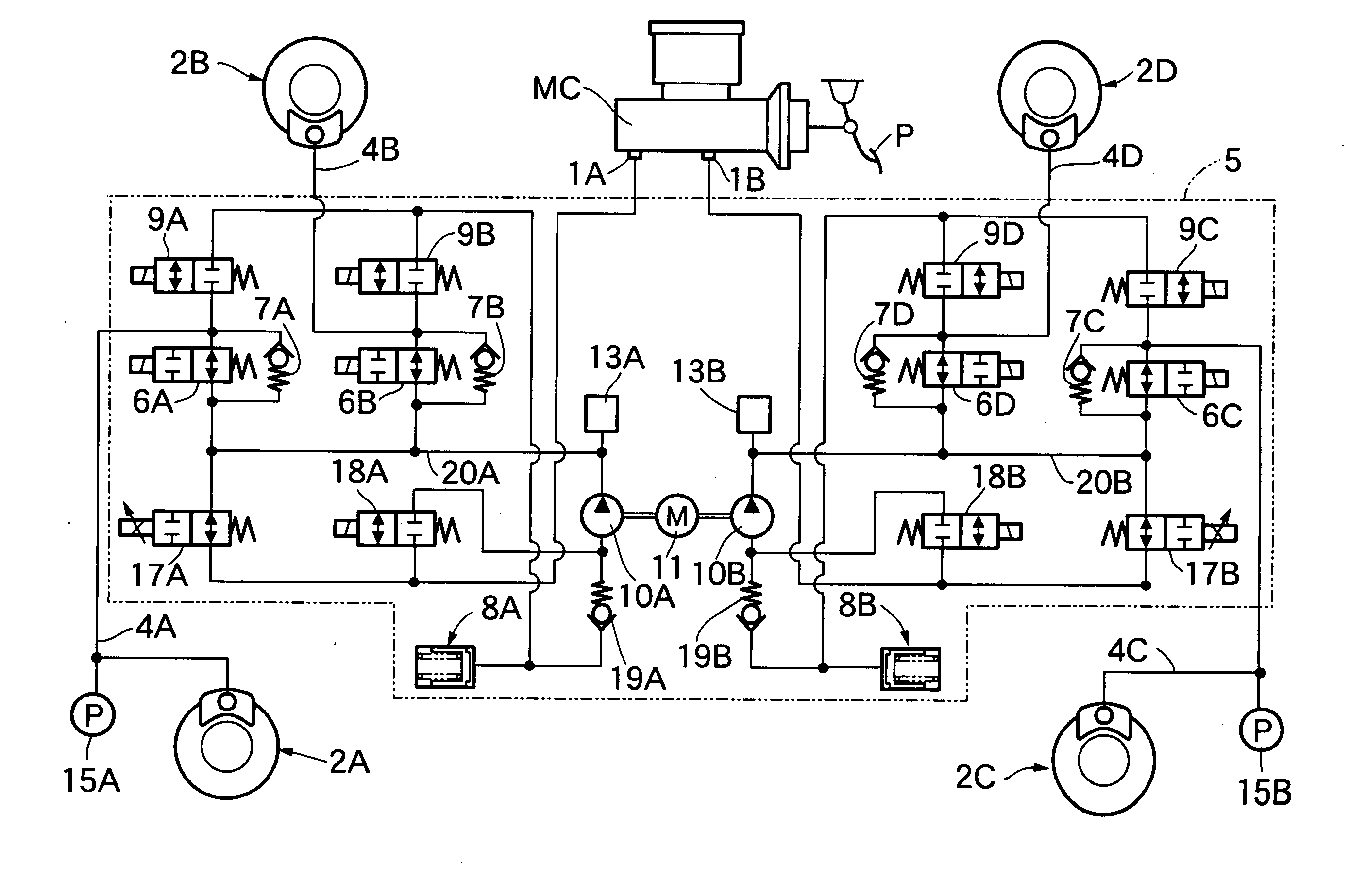
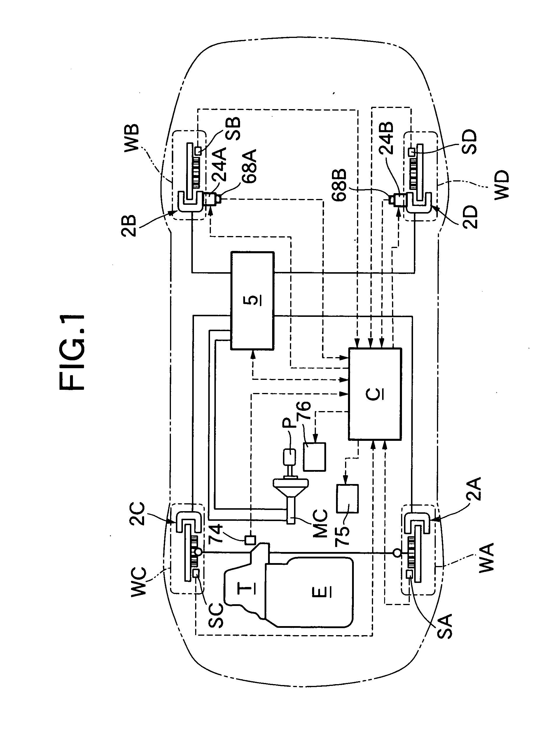
[0032] Referring first to FIG. 1, output from an automatic transmission T, connected in series to an engine E, is transmitted to a left front wheel WA and a right front wheel WC, which are driven wheels of a front-engine front-drive (FF) vehicle V. A left front wheel brake 2A and a right front wheel brake 2C, which are disk brakes, are mounted on the front wheels WA and WC. In addition, a right rear wheel brake 2B and a left rear wheel brake 2D, which are disk brakes, are mounted on a right rear wheel WB and a left rear wheel WD.

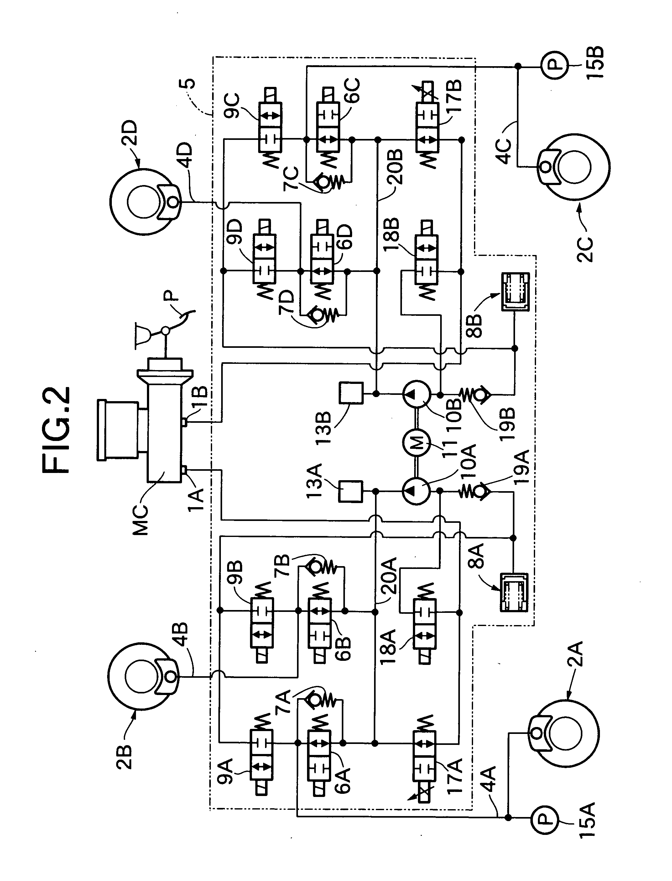
[0033] A master cylinder MC serves as a hydrau...


PUM


Abstract

A brake system for a vehicle includes an electrically operated parking brake drive device which generates an operating force for operating the wheel brakes or dedicated parking brakes in response to energization, and which operates even upon cancellation of the energization while in the operated state. A braking force related amount detector detects a physical quantity related to a braking force exhibited by each of the hydraulic pressure operated wheel brakes. When a detected physical quantity exceeds a reference value in a stopped state of the vehicle, a controller energizes the electrically operated parking brake drive device. Thus, the frequency of operation of the electrically operated parking brake drive device is decreased while eliminating inconvenient operations required to operate the electrically operated parking brake drive device, thereby reducing noise and improving durability.

Description

CROSS-REFERENCE TO RELATED APPLICATION [0001] The present invention claims priority under 35 USC 119 based on Japanese patent application No. 2005-188113, filed on Jun. 28, 2005. The subject matter of this priority document is incorporated by reference herein. BACKGROUND OF THE INVENTION [0002] 1. Field of the Invention [0003] The present invention relates to a brake system for a vehicle, comprising a hydraulic pressure generating device for outputting a hydraulic pressure corresponding to a braking operation by a vehicle driver and hydraulic pressure operated wheel brakes mounted on wheels so as to be operated based on the hydraulic pressure output from the hydraulic pressure generating device. The brake system includes an electrically operated parking brake drive device which generates an operating force for operating the wheel brakes, or dedicated parking brakes mounted on wheels separately from the wheel brakes, in response to energization thereof, and which can be maintained in...

Claims


Application Information

Patent Timeline
Patent Type & Authority Applications(United States)
IPC IPC(8): B60T8/60
CPCB60T8/32B60T13/746
Inventor NONAGA, IKUOKOAN, HIROSHIKOIKE, AKIHIKOSATO, TSUYOSHITANIGUCHI, MAKOTOKICHIMA, YUTAKAUENO, ICHIROTAKEI, KATSUYUKIKUBOSHIMA, TAKASHI
Owner HONDA MOTOR CO LTD
Why Eureka
Try Eureka