Heat dissipating apparatus

a heat dissipating apparatus and heat dissipation technology, which is applied in the direction of domestic cooling apparatus, electrical apparatus casing/cabinet/drawer, instruments, etc., can solve the problems of increasing the size of the heat dissipating apparatus, and achieve the effect of reducing the size of the apparatus, reducing noise generation, and improving cooling efficiency

Inactive Publication Date: 2005-04-21
KK TOSHIBA
View PDF16 Cites 20 Cited by
  • Summary
  • Abstract
  • Description
  • Claims
  • Application Information

AI Technical Summary

Benefits of technology

[0008] An object of the present invention is to provide a heat dissipating apparatus, which permits miniaturizing the apparatus, permits suppressing noise generation, and also permits improving the cooling efficiency.
[0011] a jet stream supply section configured to supply a jet stream to the fluid flowing in the first flowing channel in a second direction differing from the first direction so as to generate turbulence in the flow of fluid in the first flowing channel, thereby suppressing the growth of a boundary layer in the fluid within the fluid flowing channel.
[0021] supplying a jet stream into the main fluid stream flowing within the main flowing channel so as to bring about turbulence in the main fluid stream, thereby suppressing the growth of a boundary layer in the main fluid stream within the main flowing channel.

Problems solved by technology

However, the conventional heat dissipating apparatus of this type gives rise to the problem that, in accordance with the flow of fluid within the channel from the upstream side toward the downstream side, a boundary layer grows in the fluid so as to impair heat exchange function performed between the wall of the fluid flowing channel and the fluid.
However, the particular measure results in the increase in size of heat dissipating apparatus.

Method used


Image

  • Heat dissipating apparatus
  • Heat dissipating apparatus
  • Heat dissipating apparatus

Examples


first embodiment

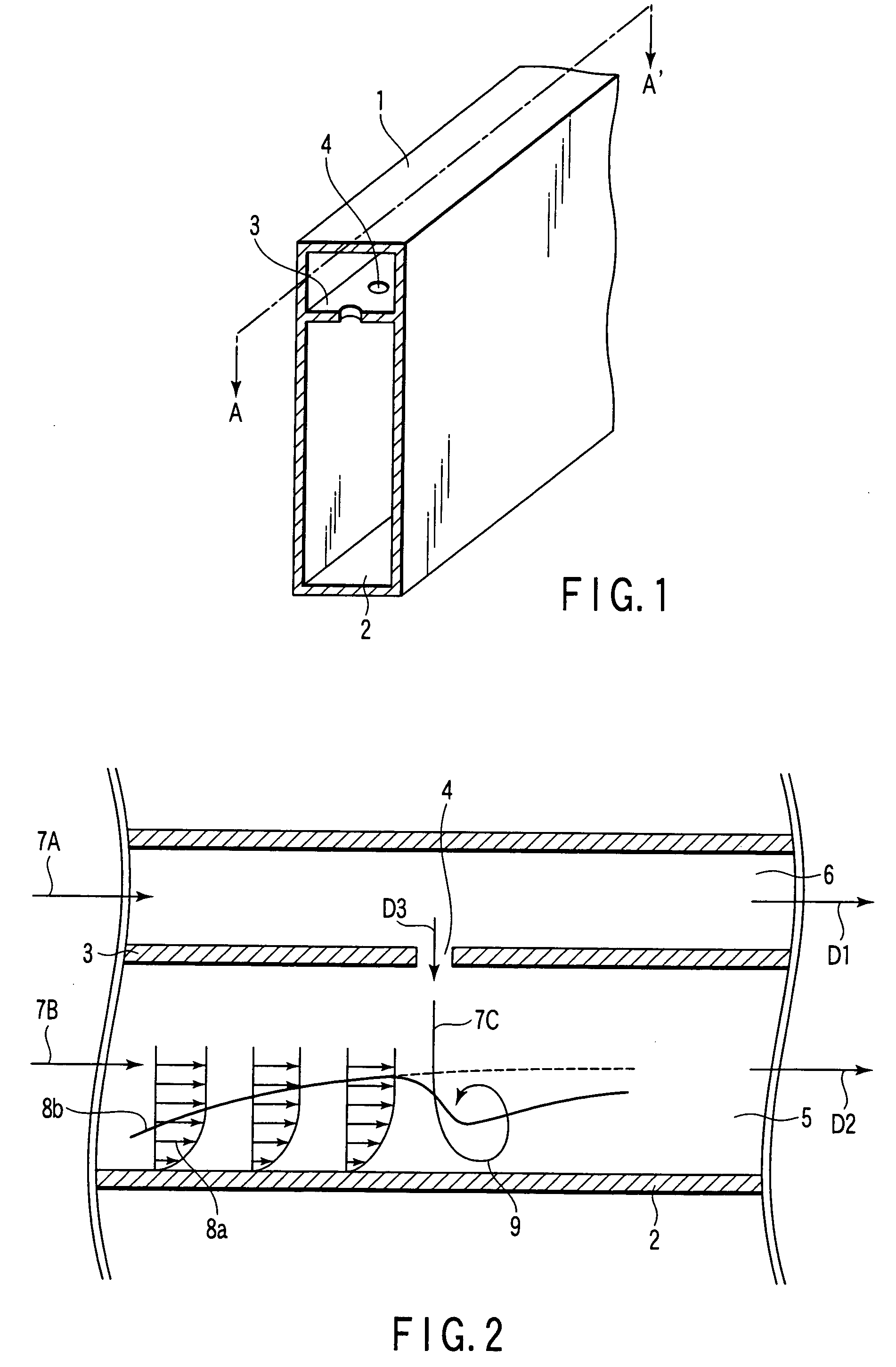
[0041]FIG. 1 is an oblique view schematically showing a configuration of a heat dissipating apparatus according to the present invention, and FIG. 2 is a cross-sectional view schematically showing the configuration of heat dissipating apparatus shown in FIG. 1 and also showing schematically the configuration of the fluid flowing channel included in heat dissipating apparatus.

[0042] A rectangular duct 1 having a rectangular cross section, which constitutes an envelope having an inlet port and an outlet port, is formed of a metal having relatively large heat conductivity such as aluminum or copper. A fluid flowing space within which flows a fluid is formed within the rectangular duct 1. A heat transfer surface 2 corresponding to the bottom surface of the rectangular duct 1 is thermally coupled to the target module to be cooled or thermally in contact with the target module to be cooled (not shown). The heat of the target module to be cooled is transferred through heat transfer surface...

second embodiment

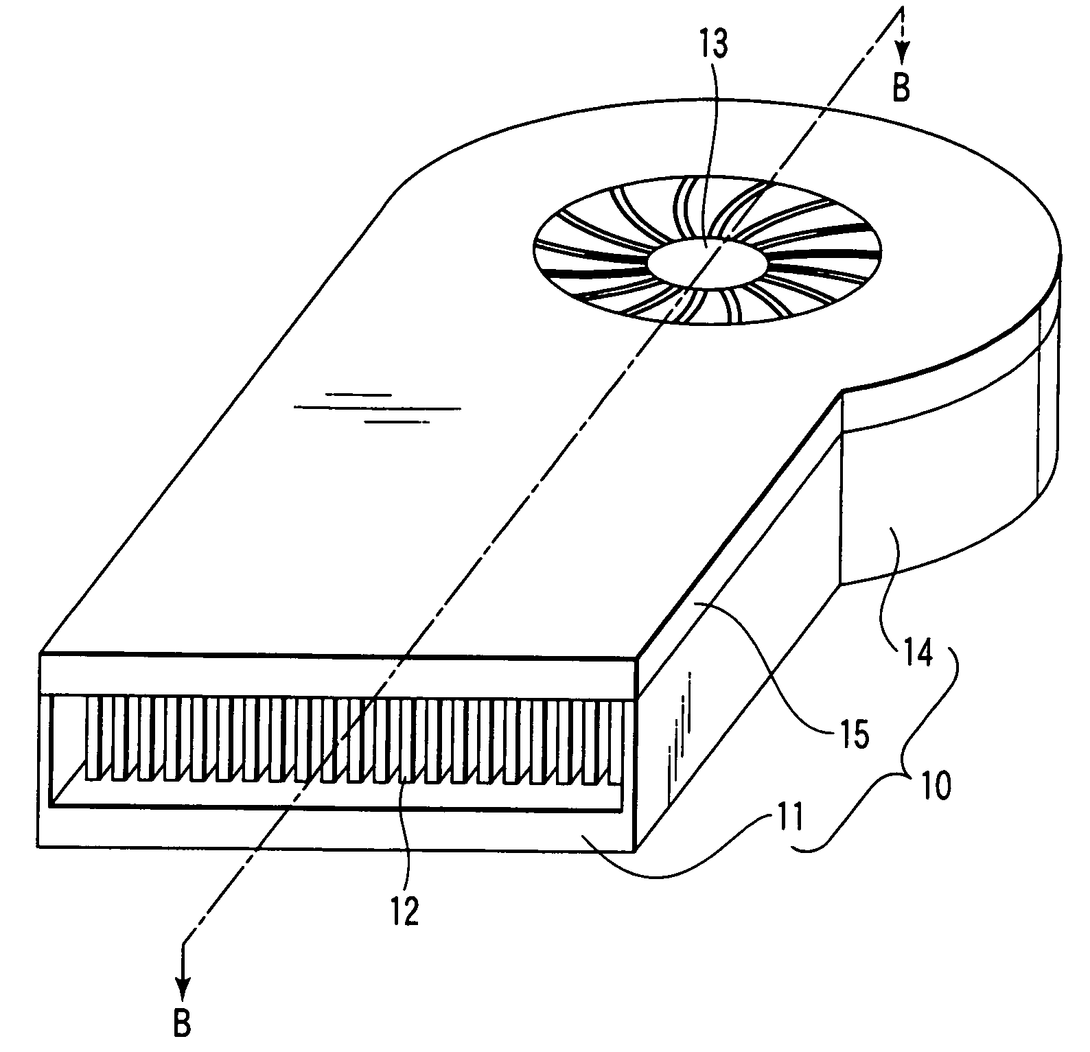
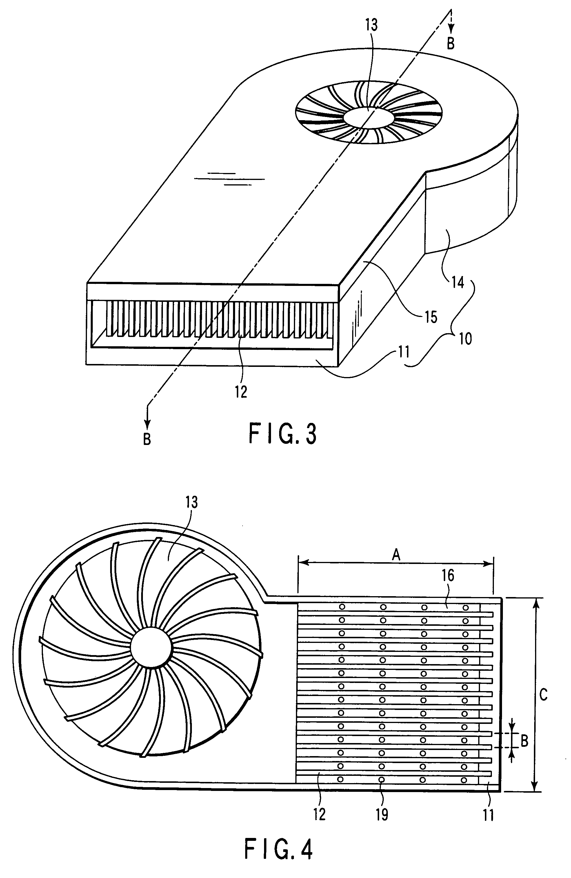
[0047] A heat dissipating apparatus according to the present invention will now be described with reference to FIGS. 3 to 6.

[0048]FIG. 3 is an oblique view schematically showing the outer appearance of heat dissipating apparatus according to the second embodiment of the present invention. FIG. 4 schematically shows the inner structure of heat dissipating apparatus shown in FIG. 3. Further, FIG. 5 is a cross section view along the line B-B shown in FIG. 3. Incidentally, a lid section 15, which is referred to herein later, is omitted from FIG. 4 for clearly showing the inner structure of heat dissipating apparatus.

[0049] In heat dissipating apparatus according to the second embodiment of the present invention, an envelope comprises a flat plate-shaped base section 11, a wall section 14 erected in a direction substantially perpendicular to the base section 11 and extending upward in a manner to surround the outer circumferential surface of the base section 11, and a lid section closin...

third embodiment

[0070] In the present invention, the main fluid stream 7B flowing within the auxiliary flowing channel 18 is divided at the connecting section 33 so as to permit the same amount of fluid to flow into each of the adjacent through-holes 19. In this case, the flow of fluid from the through-hole 19 into the main flowing channel 17 is not affected by the combination of, for example, the distance from the fin 12 and the arrangement of the through-holes 19 so as to suppress the no uniformity in the amount of fluid flowing from the through-hole 19 into the main flowing channel 17 and, thus, the flow of fluid is stabilized. Incidentally, the effect produced by the connecting section 33 can be further increased if the shape of the connecting section 33 is determined in view of the flowing-direction D1, D2 of the fluid, e.g., if the connecting section 33 is shaped arcuate or streamlined so as to permit a smooth flow of fluid.

[0071] Also, in the third embodiment of the present invention, the fi...


PUM


Abstract

One surface of a base section having an open portion forming an inlet port of a fluid is thermally connected to a target module to be cooled. Pluralities of fins arranged in parallel are mounted on the other surface of a base section in a direction substantially perpendicular to the base section. A fan is arranged to permit the fluid to flow through the clearance between the adjacent fins. A wall section open to the inlet port of the fluid is mounted on the base section. A part of the wall section constitutes a detachable lid section. A partition plate having through-holes formed therein is arranged between the base section and the lid section so as to divide the space between the base section and the lid section into two fluid flowing channels consisting of a main flowing channel and an auxiliary flowing channel.

Description

CROSS-REFERENCE TO RELATED APPLICATIONS [0001] This application is based upon and claims the benefit of priority from prior Japanese Patent Application No. 2003-304916, filed Aug. 28, 2003, the entire contents of which are incorporated herein by reference. BACKGROUND OF THE INVENTION [0002] 1. Field of the Invention [0003] The present invention relates to a heat dissipating apparatus for dissipating heat from a target module to be cooled, particularly, to a heat dissipating apparatus, in which a fluid is supplied into the fluid flowing channel within a heat dissipating apparatus, and a heat exchange is carried out between the wall surface of the channel and the fluid supplied into the channel so as to dissipate heat released from the target module to be cooled. [0004] 2. Description of the Related Art [0005] A heat dissipating apparatus utilizing a heat exchanger is widely known in the art. In recent years, many apparatuses are being made thinner and more compact. In this connection...

Claims


Application Information

Patent Timeline
Patent Type & Authority Applications(United States)
IPC IPC(8): F25D1/00G12B15/06H01C1/084H01L23/467H01L23/473H05K7/20
CPCH01L23/467H01L2924/0002H01L2924/00
Inventor DEBASHISU, BISUWASUTAKAMATSU, TOMONAOHISANO, KATSUMIIWASAKI, HIDEO
Owner KK TOSHIBA
Why Eureka
Try Eureka