Sheet feeding device

a feeding device and paper technology, applied in the direction of transportation and packaging, thin material processing, article separation, etc., can solve the problem of paper feeding noise that is usually generated, and achieve the effect of stabilizing the feeding of recording media and reducing nois

Active Publication Date: 2006-10-31
BROTHER KOGYO KK
View PDF29 Cites 21 Cited by
  • Summary
  • Abstract
  • Description
  • Claims
  • Application Information

AI Technical Summary

Benefits of technology

[0005]The object of this invention is to provide a sheet feeding device to stabilize feeding of recording media and reduce noise created by the sheet feeding roller and separation pad during the sheet feed operation.
[0007]By forming a gap between the sheet feeding roller and the separation pad so that the low friction member side is higher toward the sheet feeding roller side, the recording media does not easily contact the separation pad that creates frictional resistance, and sheet feeding noise generation can be further controlled. Therefore, when the recording media sandwiched between the surface of the sheet feeding roller and the separation pad is separated and reaches the low friction member, the frictional resistance created between the sheet feeding roller, separation pad and the recording media is reduced to allow the recording media to be fed smoothly between the separation pad and the surface of the sheet feeding roller. Therefore, paper feeding noise, and / or the like, created by the recording media feeding operation discussed above, can be controlled.

Problems solved by technology

However, in a conventional sheet feeding device, such as that disclosed above, when a sheet of paper is sandwiched between a sheet feeding roller and a separation pad and sent forward, a paper feeding noise is usually generated.

Method used


Image

  • Sheet feeding device
  • Sheet feeding device
  • Sheet feeding device

Examples


Embodiment Construction

[0035]Embodiments of the invention are explained with reference to the accompanying drawings.

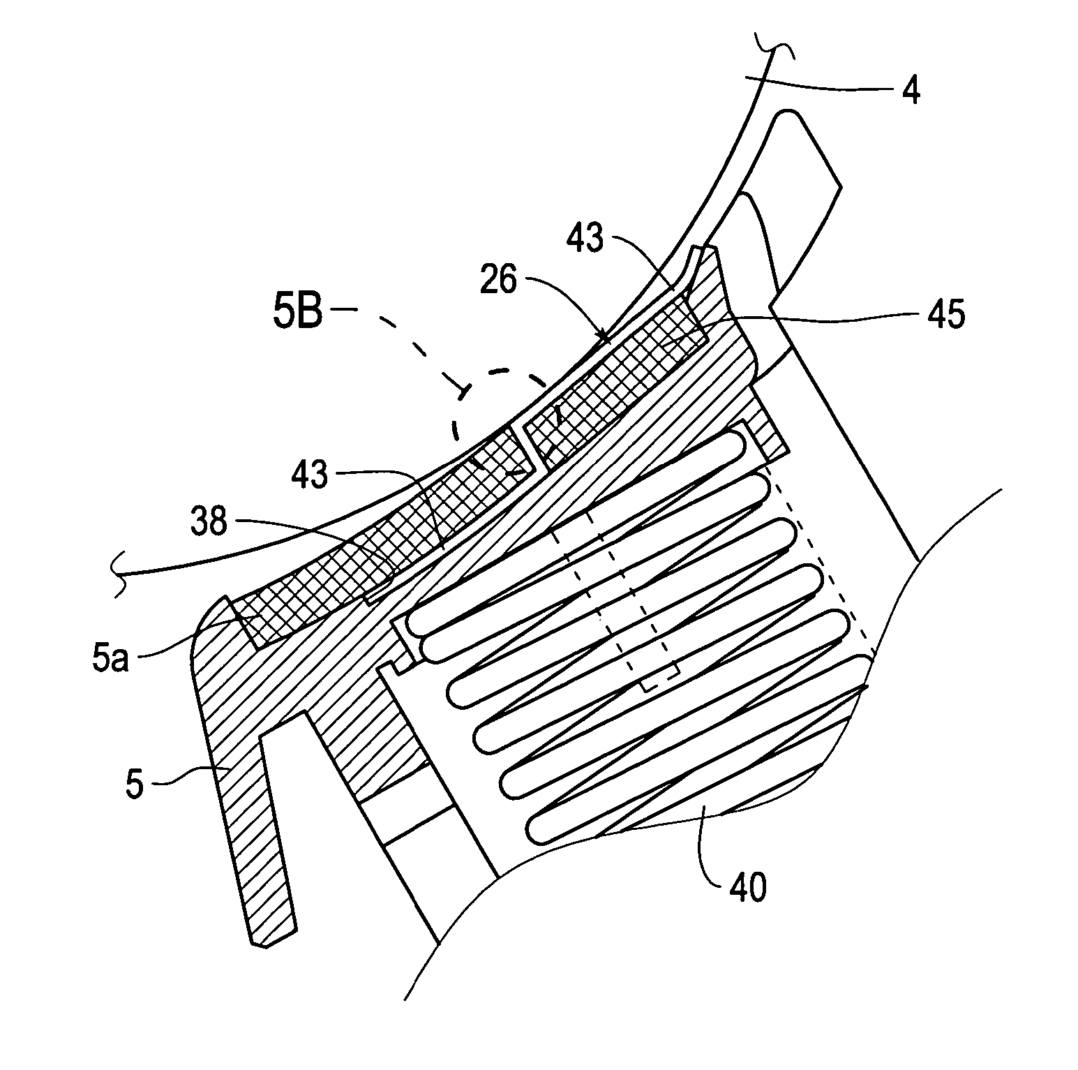
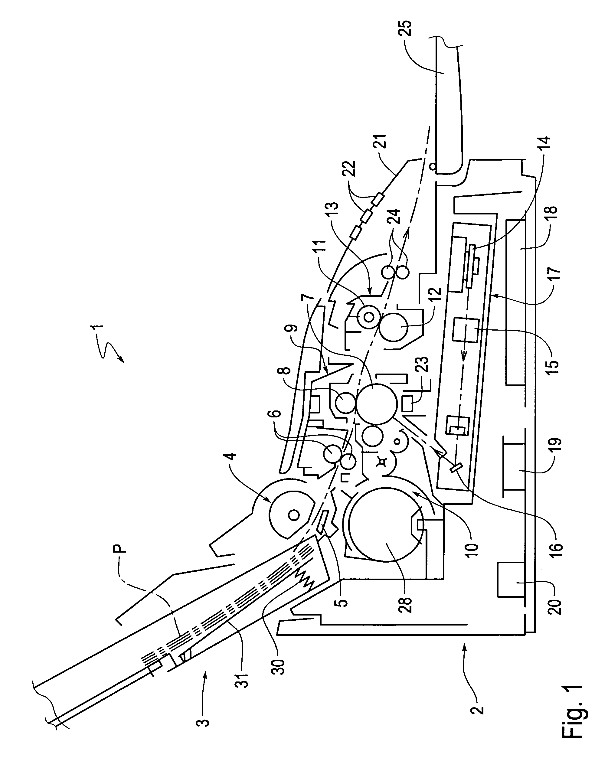
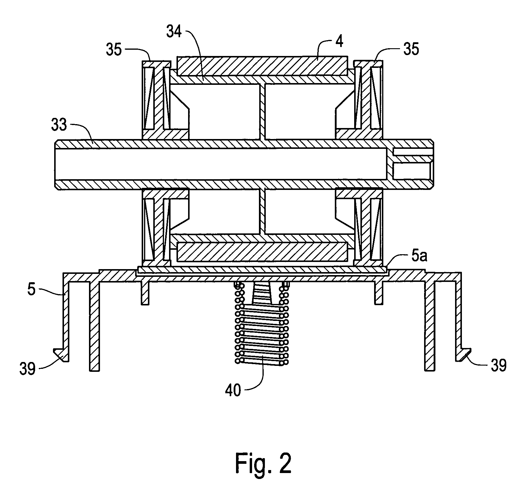
[0036]FIG. 1 shows a schematic sectional view of a printer 1, and FIG. 2 shows a main portion side cross-sectional view of a sheet feeding device.

[0037]As shown in FIGS. 1 and 2, the printer 1 includes a sheet feeding cassette 3 that can be detachably mounted on one upper side of a main body case 2. By a sheet feeding roller 4 and a separation pad 5a, sheets of paper P stacked within the sheet feeding cassette 3 are separated, one by one, and are transferred to a photosensitive body unit 9 that includes a transfer roller 8 and a photosensitive body drum 7 via a pair of transfer rollers 6. On the side of the photosensitive body unit 9 closer to the sheet feeding cassette 3 and adjacent to the photosensitive body unit 9, a developing device 10 is arranged to supply toner fed from a toner cartridge 28 to the photosensitive body drum 7. A fixing unit 13 including a heat roller 11 and a pressing ...


PUM


Abstract

A sheet feeding device includes a sheet feeding roller and a holder body. A separation pad is arranged on an upstream side, in a feeding direction of a recording medium, within a concave portion of a top surface side of the holder body facing a surface of the sheet feeding roller. On a downstream side of the concave portion adjacent to the separation pad, a low friction member is arranged in which at least a surface layer is formed of a material with a small coefficient of friction. Furthermore, a gap formation portion is formed in a surface of the concave portion where the low friction member is arranged and made higher than a surface where the separation pad is arranged. Additionally, by making the separation pad and the low friction member with the same thickness, when arranged in the concave portion, the surface of the low friction member is formed higher than the surface of the separation pad by the height of the gap formation portion.

Description

BACKGROUND OF THE INVENTION[0001]1. Field of Invention[0002]This invention relates to a sheet feeding device that separates and supplies recording media stacked in a sheet feeding portion, one by one, from the uppermost position in an image forming apparatus such as a laser beam printer, a copier, a facsimile device, or the like.[0003]2. Description of Related Art[0004]In a sheet feeding device disclosed in U.S. Pat. No. 5,584,475, an uppermost sheet of paper, among sheets of paper stacked and stored in a sheet feeding cassette, is sandwiched between a sheet feeding roller and a separation pad to separate the sheet from the stack and send the sheet forward in a sheet feeding direction. However, in a conventional sheet feeding device, such as that disclosed above, when a sheet of paper is sandwiched between a sheet feeding roller and a separation pad and sent forward, a paper feeding noise is usually generated. Therefore, in order to reduce the noise, U.S. Pat. No. 5,584,475 disclose...

Claims


Application Information

Patent Timeline
Patent Type & Authority Patents(United States)
IPC IPC(8): B65H3/52B65H3/06
CPCB65H3/0638B65H3/5223B65H2404/1112B65H2404/5311
Inventor NAKANO, HIROSHIYAMAGUCHI, TAKUYA
Owner BROTHER KOGYO KK
Why Eureka
Try Eureka