Motor control apparatus and electric power steering apparatus

a technology of motor control and electric steering, which is applied in the direction of non-deflectable wheel steering, underwater vessels, special data processing applications, etc., can solve the problem of inability to secure the duration time, and achieve the effect of suppressing the torque ripple, reducing the operating sound of the motor, and reducing the error

Active Publication Date: 2013-06-20
NSK LTD
View PDF12 Cites 21 Cited by
  • Summary
  • Abstract
  • Description
  • Claims
  • Application Information

AI Technical Summary

Benefits of technology

[0030]According to a motor control apparatus of the present invention, while using a cheap one-shunt type current detector, by calculating voltage patterns acting on each phase from PWM-ON / OFF patterns within one PWM period and their duration time and further adding a voltage fall due to motor resistance and so on, it is possible to calculate a motor current change pattern with respect to the detected current . Since it is possible to calculate a current change amount to the detected current within one PWM period, it is possible to correct the detected each-phase motor current values so as to correspond to the motor average current value by adding the calculated current change amount as the correction value. Further, since it is possible to eliminate or reduce an error between the detected current and the average current that becomes a problem in one-shunt type current detection by the current correction, it is possible to realize a motor control apparatus that has less motor's operating sound and suppresses the torque ripple.
[0031]Further, in the case of applying the motor control apparatus of the present invention to an electric power steering apparatus, since it is possible to suppress occurrences of noises and handle's ripples, it is possible to employ the one-shunt type current detection while keeping steering performances, and it is possible to realize cost-cutting and weight saving.

Problems solved by technology

Therefore, although it is necessary to maintain a one-phase ON-state and a two-phase ON-state for a necessary time for the current detection, in the case that each-phase duty command values become equal to each other, a problem that it is impossible to secure that a duration time, arises.

Method used


Image

  • Motor control apparatus and electric power steering apparatus
  • Motor control apparatus and electric power steering apparatus
  • Motor control apparatus and electric power steering apparatus

Examples


first embodiment

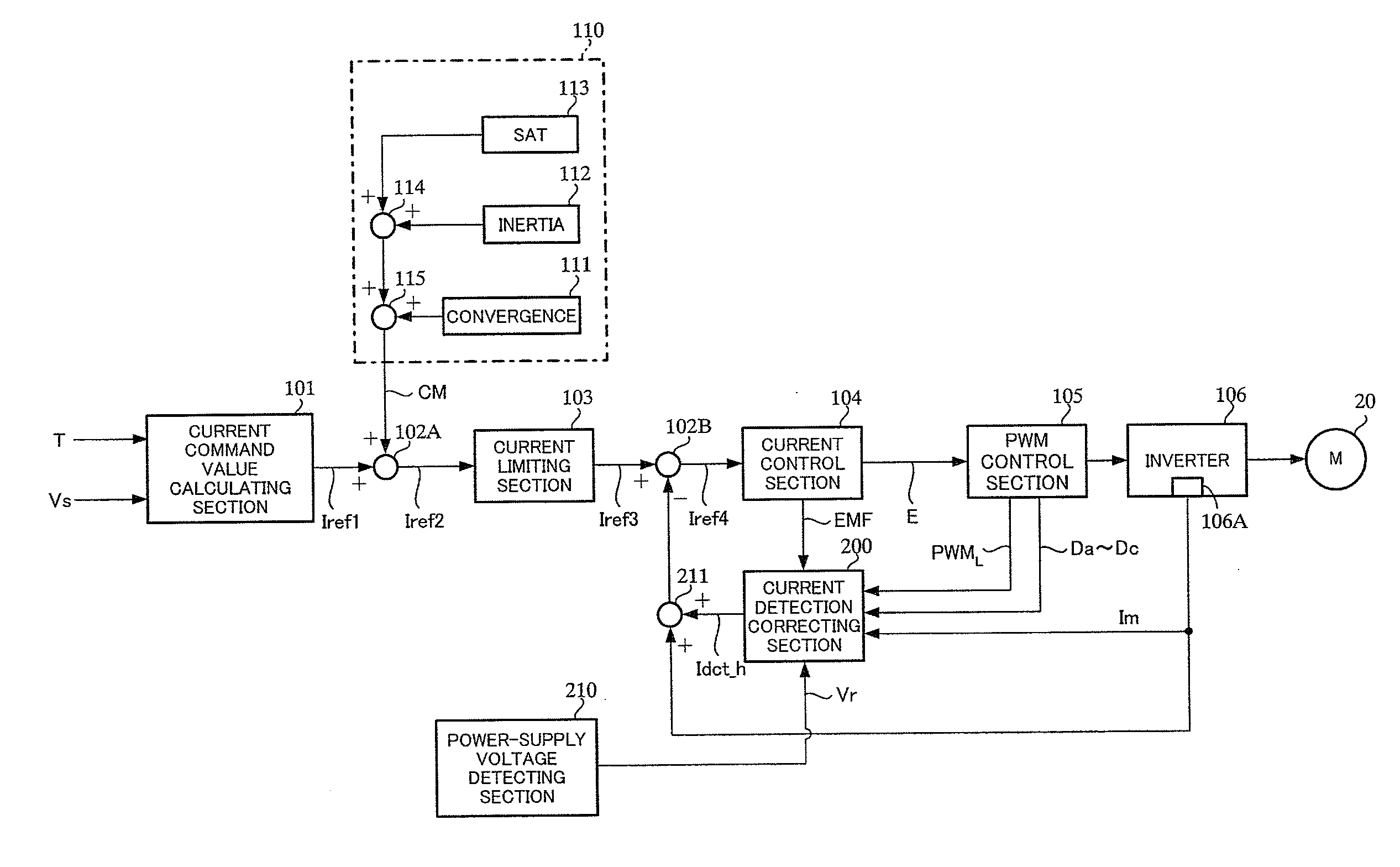
[0086]In the above-described first embodiment, although the given timing is arranged at seven points (S0˜S6) within one PWM period, by being limited to three points of timings, i.e. a start point, a middle point and an end point of one PWM period, internal calculations are simplified, and it becomes possible to calculate the current detection correction value Idct_h with few task load.

second embodiment

[0087]As shown in FIG. 15, the given timings are the start point (the timing S0) of one PWM period before the current detection timing for the A-phase, the middle point (the timing S1) after the current detection timing for the A-phase, and the end point (the timing S2) after the current detection timing for the A-phase. In the second embodiment that sets the given timings as three points, the output of each section of the internal configuration of the current detection correcting section 200 changes as follows, since the calculation itself becomes few, the task load can be substantially reduced.

[0088]That is, the output of the PWM-ON / OFF pattern duration time calculating section 201 is simplified as shown in FIG. 16. In the current change amount calculating section 202 for the applied voltage component, in the example of FIG. 15, since the timing S0 is located before the A / D timing, the current change amount caused by applied voltage at the timing S0 is calculated by the following ...


PUM


Abstract

A motor control apparatus that drive-controls a motor by an inverter based on each-phase duty command values of PWM and detects each-phase motor currents of the motor by a one-shunt type current detector. The apparatus includes a current detection correcting section that calculates a current detection correction value based on a power-supply voltage of the motor, each-phase duty command values, a back-EMF information of the motor, each-phase motor currents detected by the current detector, arrangement information of the PWM, and electric characteristic formula of the motor, thereby to correct the each-phase motor currents detected by the current detector to a motor average current by the current detection correction value and drive-controls the motor.

Description

TECHNICAL FIELD[0001]The present invention relates to a motor control apparatus that is drive-controlled by duty command values of PWM (Pulse Width Modulation) and an electric power steering apparatus that provides a steering system of a vehicle with a steering assist force by means of the motor control apparatus, and in particular to a motor control apparatus that has less operating sound and reduces torque ripples and an electric power steering apparatus mounting the same.BACKGROUND ART[0002]An electric power steering apparatus that energizes a steering apparatus of a vehicle by using a rotational torque of a motor as an assist torque, applies a driving force of the motor as the assist torque to a steering shaft or a rack shaft by means of a transmission mechanism such as gears or a belt through a reduction mechanism. And then, in order to supply a current to the motor so that the motor generates a desired torque, an inverter is used in a motor drive circuit.[0003]A general config...

Claims


Application Information

Patent Timeline
Patent Type & Authority Applications(United States)
IPC IPC(8): B62D5/04H02P27/08B62D6/00B62D119/00H02P6/06H02P6/08H02P6/16H02P6/28
CPCB62D5/046H02P6/10H02P6/002H02P27/085H02M7/5387H02P27/08H02P6/28H02M1/0009
Inventor IMAMURA, YOUSUKEMORI, KENJIMAEDA, MASAHIRO
Owner NSK LTD
Why Eureka
Try Eureka