3D pointing device and method for compensating movement thereof

a pointing device and three-dimensional technology, applied in the direction of instruments, computing, electric digital data processing, etc., can solve the problems of accumulated errors, unable to angles and directions the compensation disclosed therein cannot accurately or properly calculate or obtain the movements of the pointing device, etc., to eliminate the accumulation of errors, accurate output and obtained

Active Publication Date: 2013-05-14
CYWEE GROUP
View PDF19 Cites 2 Cited by
  • Summary
  • Abstract
  • Description
  • Claims
  • Application Information

AI Technical Summary

Benefits of technology

[0013]According to another aspect of the present invention, the present invention provides an enhanced comparison method to eliminate the accumulated errors as well as noises over time associated with signals generated by a combination of motion sensors, including the ones generated by accelerometers Ax, Ay, Az and the ones generated by gyroscopes ωx, ωy, ωz in dynamic environments. In other words, accumulated errors associated with a fusion of signals from a motions sensor module comprising a plurality of motion sensors to detect movements on and rotations about different axes of a reference frame may be eliminated or corrected.
[0014]According to still another aspect of the present invention, the present invention provides an enhanced comparison method to correctly calculating and outputting a resulting deviation comprising a set of resultant angles including yaw, pitch and roll angles in a spatial pointer frame, preferably about each of three orthogonal coordinate axes of the spatial pointer reference frame, by comparing signals of rotation sensor related to angular velocities or rates with the ones of accelerometer related to axial accelerations such that these angles may be accurately outputted and obtained, which may too be further mapping to another reference frame different from said spatial pointer frame.
[0016]According to another example embodiment of the present invention, a 3D pointing device utilizing a six-axis motion sensor module with an enhanced comparison method for eliminating accumulated errors of said six-axis motion sensor module to obtain deviation angles corresponding to movements and rotations of said 3D pointing device in a spatial pointer reference frame is provided. The 3D pointing device and the comparison method provided by the present invention by comparing signals from the abovementioned six-axis motion sensor module capable of detecting rotation rates or angular velocities of the 3D pointing device about all of the XP, YP and ZP axes as well as axial accelerations of the 3D pointing device along all of the XP, YP and ZP axes. In other words, the present invention is capable of accurately outputting the abovementioned deviation angles including yaw, pitch and roll angles in a 3D spatial pointer reference frame of the 3D pointing device to eliminate or reduce accumulated errors and noises generated over time in a dynamic environment including conditions such as being subject to a combination of continuous movements, rotations, external gravity forces and additional extra accelerations in multiple directions or movement and rotations that are continuously nonlinear with respect to time; and furthermore, based on the deviation angles being compensated and accurately outputted in 3D spatial pointer reference frame may be further mapped onto or translated into another reference frame such as the abovementioned display frame, for example a reference in two-dimension (2D).
[0018]According to another example embodiment of the present invention, a method for compensating accumulated errors of signals of the abovementioned six-axis motion sensor module in dynamic environments associated in a spatial pointer reference frame is provided. In one embodiment, the method may be performed or handled by a hardware processor. The processor is capable of compensating the accumulated errors associated with the resultant deviation in relation to the signals of the above-mentioned six-axis motion sensor module of the 3D pointing device subject to movements and rotations in a spatial pointer reference frame and in a dynamic environment by performing a data comparison to compare signals of rotation sensor related to angular velocities with the ones of accelerometer related to axial accelerations such that the resultant deviation corresponding to the movements and rotations of the 3D pointing device in the 3D spatial pointer frame may be obtained accurately over time in the dynamic environments.

Problems solved by technology

The pointing device by Liberty utilizing a 5-axis motion sensor may not output deviation angles of the pointing device in, for example, a 3D reference frame; in other words, due to due to the limitation of the 5-axis motion sensor of accelerometers and gyro-sensors utilized therein, the pointing device by Liberty cannot output deviation angles readily in 3D reference frame but rather a 2D reference frame only and the output of such device having 5-axis motion sensors is a planar pattern in 2D reference frame only.
In addition, it has been found that the pointing device and compensation disclosed therein cannot accurately or properly calculate or obtain movements, angles and directions of the pointing device while being subject to unexpected dynamic movement during the obtaining of the signals generated by the motion sensors, in particular, during unexpected drifting movements and / or accelerations along with the direction of gravity.
In other words, it has been found that dynamic actions or extra accelerations including additional accelerations, in particular the one acted upon the direction substantially parallel to or along with the gravity imposed on the pointing device with the compensation methods provided by Liberty, said pointing device by Liberty cannot properly or accurately output the actual yaw, pitch and roll angles in the spatial reference frame XPYPZP and following which, consequently, the mapping of the spatial angles onto any 2D display reference frame such as XDYDZD may be greatly affected and erred.
Furthermore, the reading of the accelerometer may be accurate only when the pointing device is static since due to the limitation on known accelerometers that these sensors may not distinguish the gravitational acceleration from the acceleration of the forces including centrifugal forces or other types of additional accelerations imposed or exerted by the user.
Furthermore, it has been found that known prior arts may only be able to output a “relative” movement pattern in a 2D reference frame based on the result calculated from the signals of motion sensors.
Such relative movement from the previous location to the next location with respect to time cannot accurately determine and / or output the next location, particularly in situations where the previous location may have been an erred location or have been faultily determined as an incorrect reference point for the next location that is to be calculated therefrom and obtained based on their relative relationship adapted.

Method used


Image

  • 3D pointing device and method for compensating movement thereof
  • 3D pointing device and method for compensating movement thereof
  • 3D pointing device and method for compensating movement thereof

Examples


Embodiment Construction

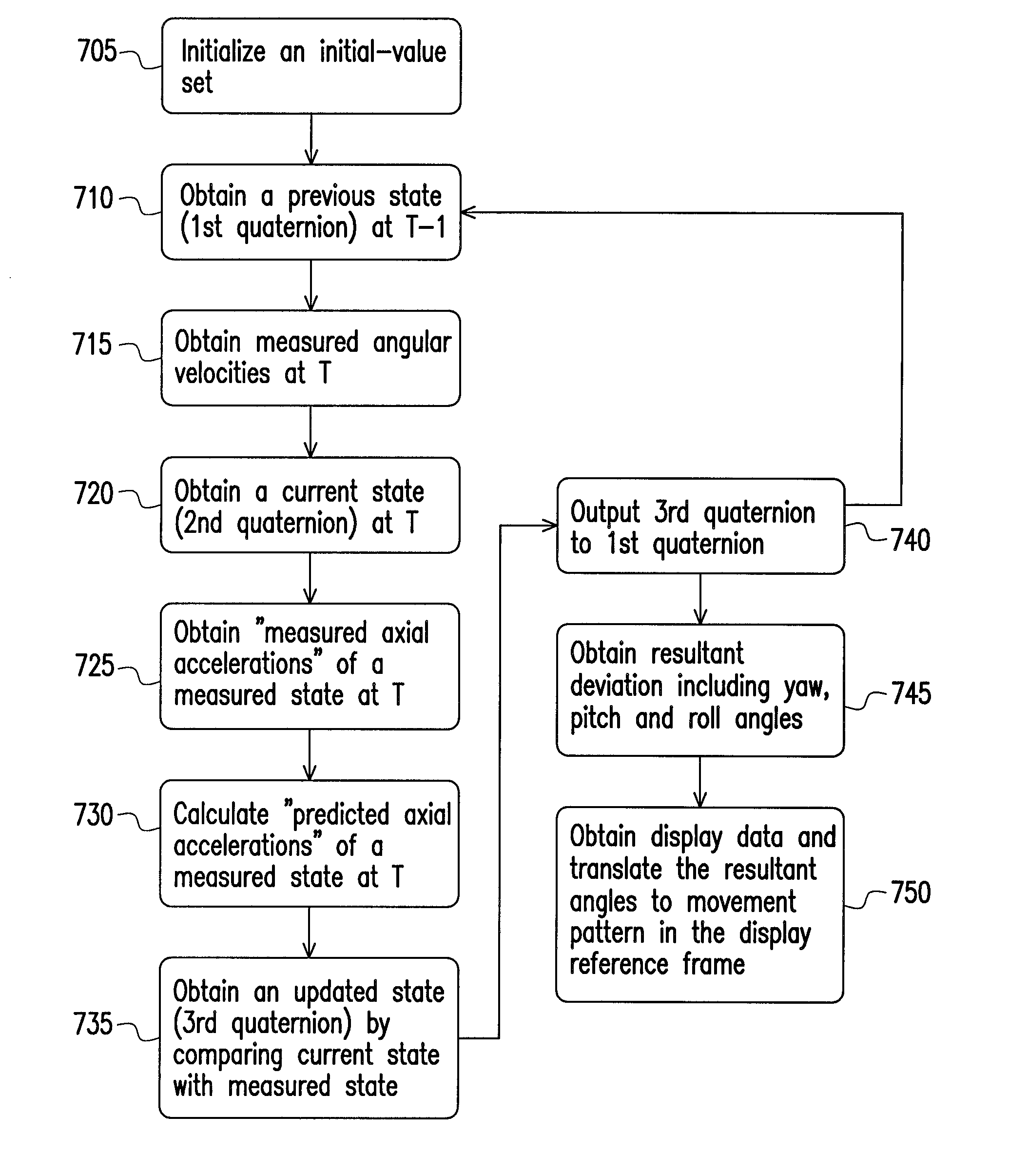
[0031]Reference will now be made in detail to the present embodiments of the invention, examples of which are illustrated in the accompanying drawings. Wherever possible, the same reference numbers are used in the drawings and the description to refer to the same or like parts.

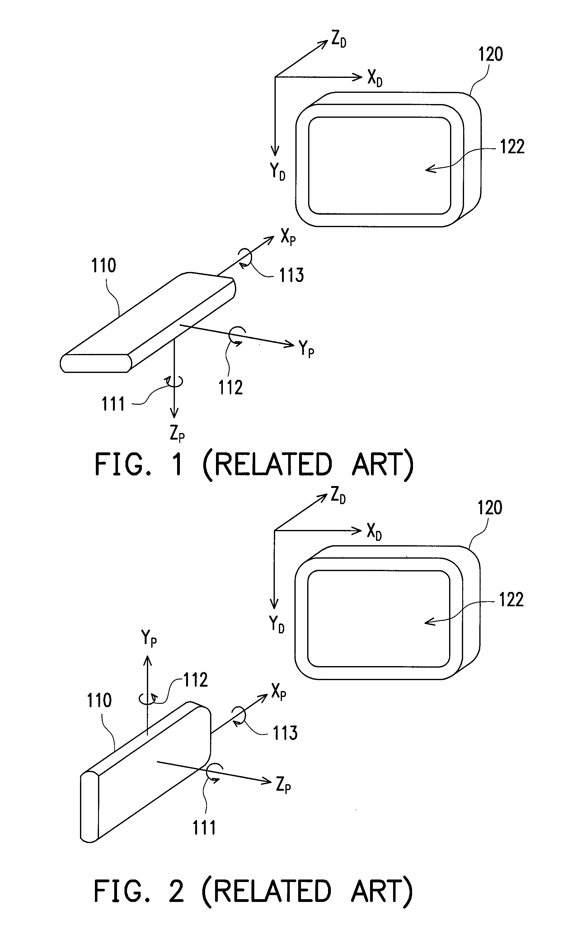
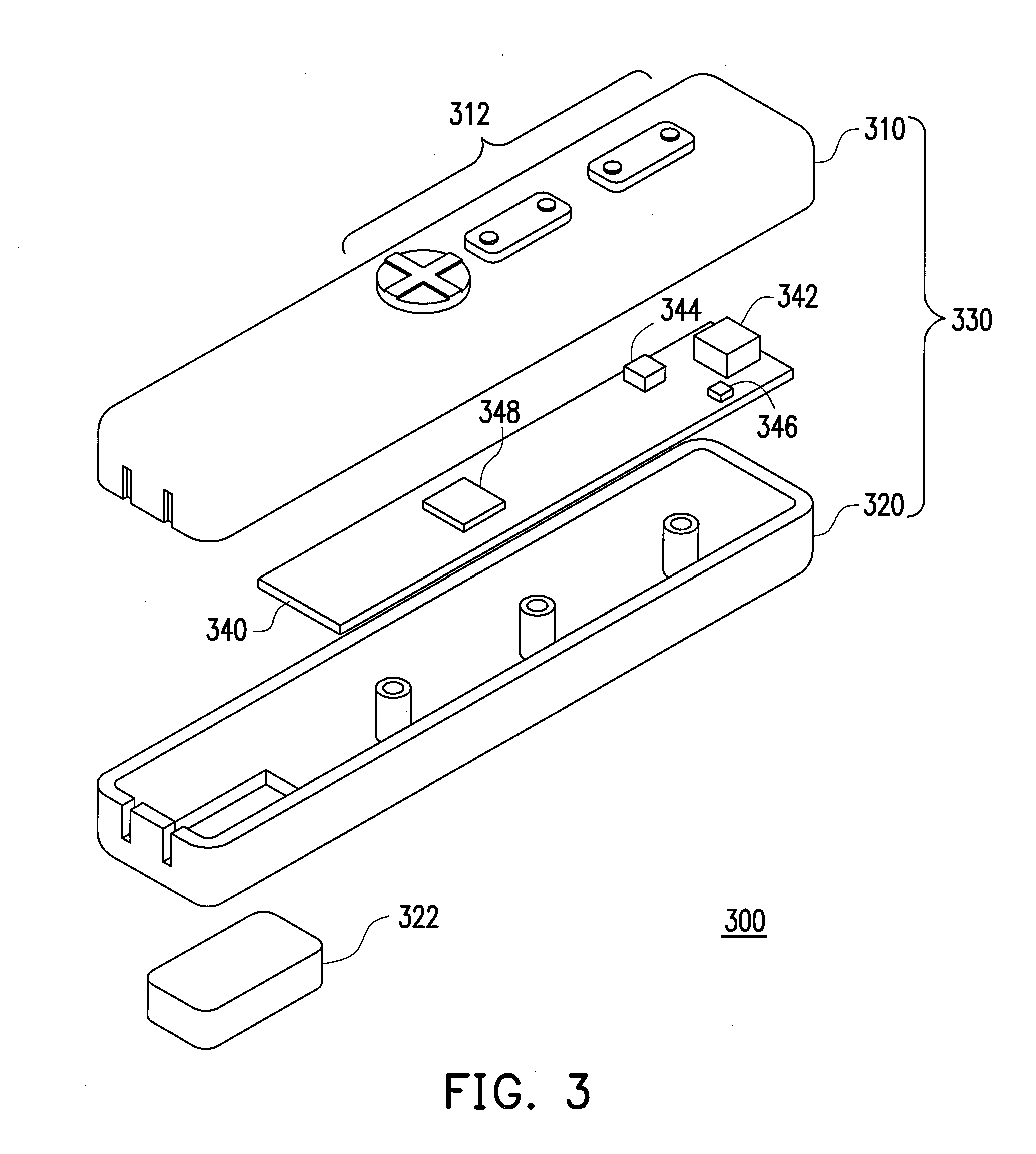
[0032]FIG. 3 is an exploded diagram showing a 3D pointing device 300 according to an embodiment of the present invention. The 3D pointing device 300 is subject to movements and rotations in dynamic environments in a 3D spatial pointer reference frame. The spatial pointer reference frame is analogous to the reference frame XPYPZP in FIG. 1 and FIG. 2. The movements and rotations of the 3D pointing device 300 in the aforementioned dynamic environments in the spatial pointer reference frame may be continuously nonlinear with respect to time.

[0033]The 3D pointing device 300 includes a top cover 310, a printed circuit board (PCB) 340, a rotation sensor 342, an accelerometer 344, a data transmitting unit 346, a comp...


PUM


Abstract

A three-dimensional (3D) pointing device capable of accurately outputting a deviation including yaw, pitch and roll angles in a 3D reference frame and preferably in an absolute manner is provided. Said 3D pointing device comprises a six-axis motion sensor module including a rotation sensor and an accelerometer, and a processing and transmitting module. The six-axis motion sensor module generates a first signal set comprising angular velocities and a second signal set comprising axial accelerations associated with said movements and rotations of the 3D pointing device in the 3D reference frame. The processing and transmitting module utilizes a comparison method to compare the first signal set with the second signal set to obtain an updated state of the six-axis motion sensor module based on a current state and a measured state thereof in order to output the resulting deviation in the 3D reference frame and preferably in an absolute manner.

Description

CROSS-REFERENCE TO RELATED APPLICATION[0001]This application claims priority benefits of U.S. Patent Provisional Application No. 61 / 292,558, filed on Jan. 6, 2010. The entirety of the above-mentioned patent applications is hereby incorporated by reference herein and made a part of this specification.BACKGROUND OF THE INVENTION[0002]1. Field of the Invention[0003]The present invention generally relates to a three-dimensional (3D) pointing device utilizing a motion sensor module and method of compensating and mapping signals of the motion sensor module subject to movements and rotations of said 3D pointing device. More particularly, the present invention relates to a 3D pointing device utilizing a six-axis motion sensor module with an enhanced comparison to calculate and compensate accumulated errors associated with the motion sensor module and to obtain actual resulting deviation angles in spatial reference frame and under dynamic environments.[0004]2. Description of the Related Art[...

Claims


Application Information

Patent Timeline
Patent Type & Authority Patents(United States)
IPC IPC(8): G09G5/00G06F3/038
CPCG06F3/0346G06F3/0383G09G5/00
Inventor YE, ZHOULI, CHIN-LUNGLIOU, SHUN-NAN
Owner CYWEE GROUP
Why Eureka
Try Eureka