Imaging device and biometrics authentication apparatus

a biometric authentication and imaging device technology, applied in the field of imaging devices and biometric authentication apparatuses, can solve the problems of low risk of a threat to safety and security due to theft or the like, low possibility of forgery, and reduce the possibility that a person who undergoes the authentication process feels psychologically stressed, so as to achieve the effect of suppressing the occurrence of nois

Inactive Publication Date: 2010-06-01
MAXELL HLDG LTD
View PDF11 Cites 20 Cited by
  • Summary
  • Abstract
  • Description
  • Claims
  • Application Information

AI Technical Summary

Benefits of technology

[0015]The present invention has been accomplished to address the above concern, and an object of the present invention is thus to provide an imaging device and a biometric authentication apparatus capable of suppressing the occurrence of noise effectively.
[0018]In such a configuration, it is possible to prevent information coming from an area other than a desired imaging area from entering a photoreceptor, thereby effectively suppressing the occurrence of noise.
[0027]In such a configuration, it is possible to prevent information coming from an area other than a desired imaging area from entering a photoreceptor, thereby effectively suppressing the occurrence of noise.

Problems solved by technology

Further, because there is also no possibility of loss unlike a key or the like, the risk of a threat to safety and security due to theft or the like is low.
Thus, the use of blood vessel patterns reduces the possibility that a person who undergoes the authentication process feels psychologically stressed.
Further, because the authentication method using blood vessel patterns utilizes the information in vivo, the possibility of forgery is low.
However, there is a limit to the size and thickness reduction for its lens structure.
This results in further degradation of the quality of a signal from the photoreceptor 11A.
This is a serious problem in reducing the thickness of an imaging device.

Method used


Image

  • Imaging device and biometrics authentication apparatus
  • Imaging device and biometrics authentication apparatus
  • Imaging device and biometrics authentication apparatus

Examples


first embodiment

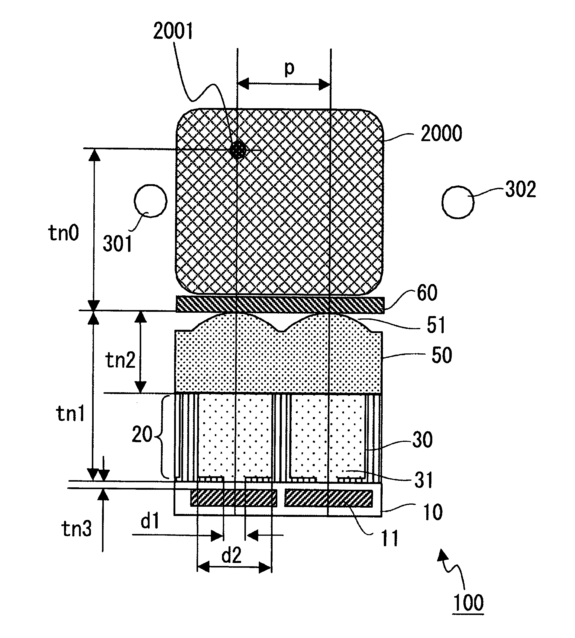
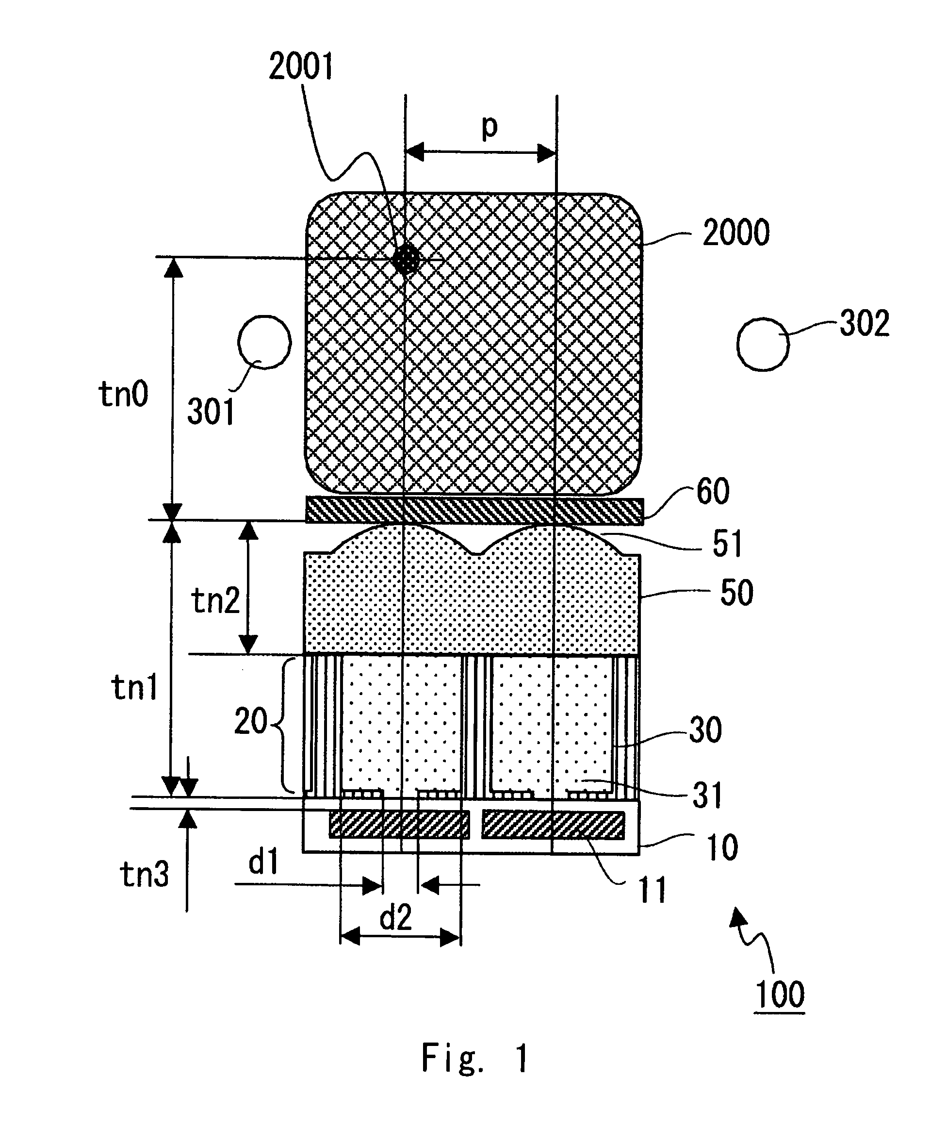
[0081]The structure of a biometric authentication apparatus according to a first embodiment of the present invention is described hereinafter. FIG. 1 is a sectional view schematically showing the structure of an imaging device of the biometric authentication apparatus according to this embodiment. FIG. 2 is a block diagram showing the configuration of the biometric authentication apparatus according to an embodiment of the present invention. The dimensions shown in FIG. 1 indicate actual lengths.

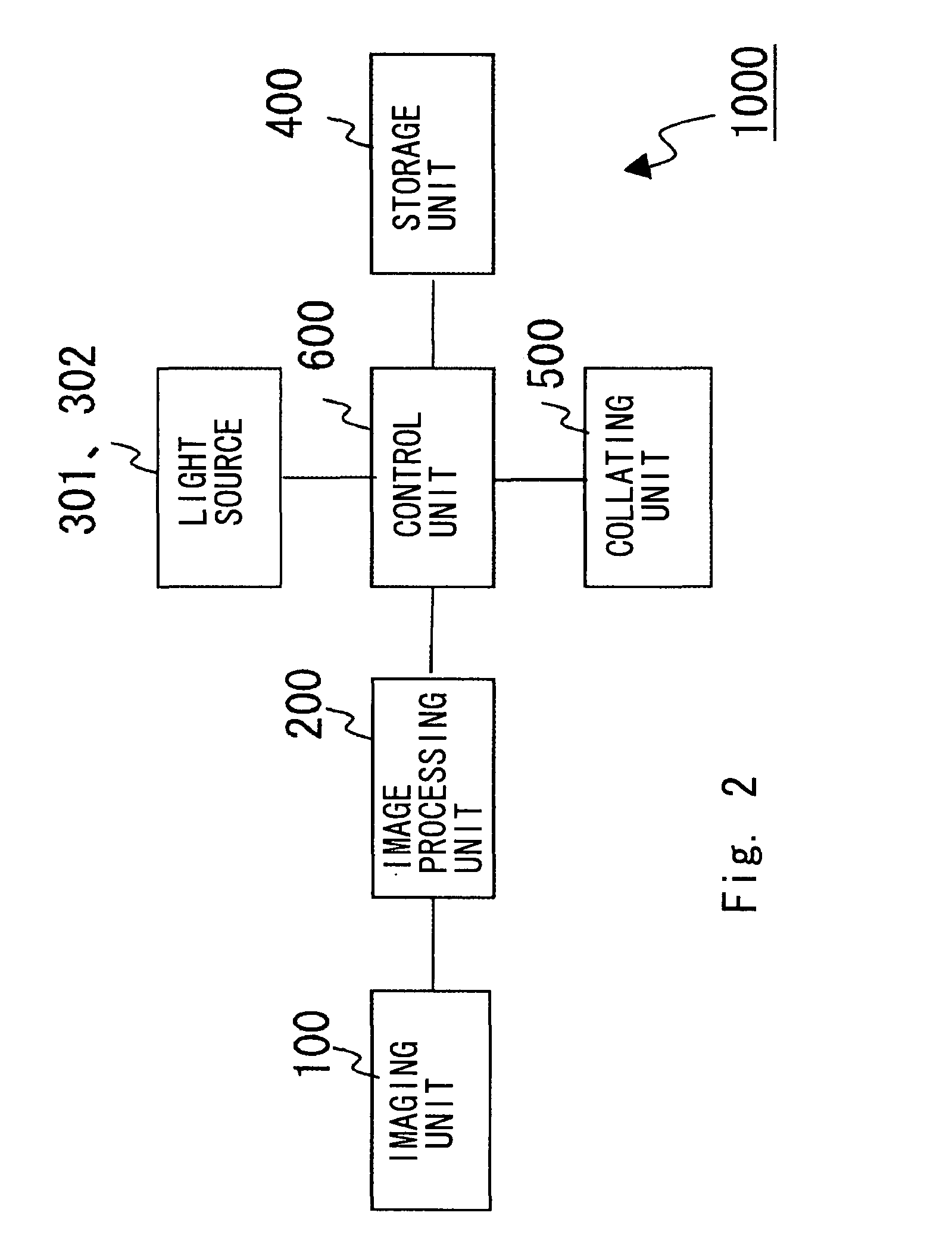
[0082]Referring first to FIG. 2, a biometric authentication apparatus 1000 according to the first embodiment of the invention includes an imaging unit 100, an image processing unit 200, light sources 301 and 302, a storage unit 400, a collating unit 500, and a control unit 600.

[0083]The imaging unit 100 is connected with an image processing unit 200. The imaging unit 100 captures an image of a pattern of vein 2001 of a finger 2000 (biometric information). Near-infrared rays from the light so...

second embodiment

[0168]The structure of a biometric authentication apparatus according to a second embodiment of the present invention is described hereinafter. FIG. 4 schematically shows the structure of an imaging unit 101 in the biometric authentication apparatus of the second embodiment. The dimensions shown in FIG. 4 indicate actual lengths.

[0169]In the first embodiment, a plurality of microlenses 51 are formed on the upper surface of the microlens array 50. On the other hand, in the second embodiment, a plurality of microlenses 51 are formed on the lower surface of the microlens array 50 as shown in FIG. 4.

[0170]Further, in the first embodiment, the optical filter 60 is a separate component from the microlens array 50. On the other hand, in the second embodiment, a visible light absorbing layer 80 and a hard-coat layer 70 are formed on top of the microlens array 50 as shown in FIG. 4. The optical filter 60 is thereby integrated with the microlens array 51. The visible light absorbing layer 80 ...

third embodiment

[0194]The structure of a biometric authentication apparatus according to a third embodiment of the present invention is described hereinafter. FIG. 5 schematically shows the structure of an imaging unit in the biometric authentication apparatus of the third embodiment. The dimensions shown in FIG. 5 indicate actual lengths. In the embodiments to be described in the followings (the third to fifth embodiments), a biometric authentication apparatus is used in the wavelength range of 600 nm to 1200 nm. In the following embodiments, the effects of parameters are examined in further detail than in the above-described embodiments.

[0195]The structure of an imaging unit 102 of this embodiment is briefly described hereinafter with reference to FIG. 5. The imaging unit 102 includes the photoreceptor portion 10, the light shielding layer 20, the microlens array 50 and the optical filter 60, which are arranged in this order.

[0196]In the photoreceptor portion 10, a plurality of photoreceptors 11 ...


PUM


Abstract

An imaging device includes a photoreceptor portion including a plurality of photoreceptors arranged in an array, a microlens array including a plurality of microlenses, and a light shielding layer placed between the photoreceptor portion and the microlens array. The light shielding layer has apertures located corresponding to the plurality of photoreceptors. An optical relationship of an actual length d1 of an aperture width of the apertures on a side of the photoreceptors, an actual length p of a distance between adjacent microlenses, an equivalent air length t0 of a distance between vein and a top of the microlenses, and an equivalent air length t1 of a thickness between the top of the microlenses and an aperture position of the apertures on the side of the photoreceptors satisfies:1.36×t⁢⁢1p≤d⁢⁢1≤2.4×t⁢⁢1p+p×t⁢⁢1t⁢⁢0.

Description

BACKGROUND OF THE INVENTION[0001]1. Field of the Invention[0002]The present invention relates to an imaging device and a biometrics authentication apparatus.[0003]2. Description of Related Art[0004]Biometric authentication technology using human body characteristics such as fingerprints, irises and blood vessel patterns receives attention as a new security system. The biometric authentication technology offers convenience because there is no need to take along unlike a key or the like. Further, because there is also no possibility of loss unlike a key or the like, the risk of a threat to safety and security due to theft or the like is low.[0005]Particularly, an authentication method using blood vessel patterns in a human finger or the like is not associated with criminal investigation unlike the method using fingerprints and does not require the application of light to eyeballs unlike the method using irises. Thus, the use of blood vessel patterns reduces the possibility that a pers...

Claims


Application Information

Patent Timeline
Patent Type & Authority Patents(United States)
IPC IPC(8): H04N5/225
CPCG06K9/00033G06K2009/00932G06K2009/0006G06V40/1341G06V40/1312G06V40/14
Inventor KISHIGAMI, MASAHIROUMEBAYASHI, NOBUHIRO
Owner MAXELL HLDG LTD
Why Eureka
Try Eureka