Vibrating wet shaver

a wet shaver and wet shaver technology, applied in the direction of metal working apparatus, etc., can solve the problems of increasing the cost of the shaver manufacturing process, and achieve the effect of convenient manufacturing process, convenient shaver manufacturing process and easy obtaining precise tolerances

Inactive Publication Date: 2009-05-14
BIC VIOLEX SA
View PDF7 Cites 21 Cited by
  • Summary
  • Abstract
  • Description
  • Claims
  • Application Information

AI Technical Summary

Benefits of technology

[0022]the casing of the vibratory is substantially circular in cross section and has two diametrically opposed portions clamped between the side surfaces of the first bearing surface, which facilitates the manufacturing process of the shaver;
[0023]the elastomeric layer is more compressed in the second transverse direction between the two side surfaces of the first bearing surface than i

Problems solved by technology

U.S. Pat. No. 5,299,354 discloses an example of such a known vibrating shaver, in which the intimate contact between the casing of the electri

Method used


Image

  • Vibrating wet shaver
  • Vibrating wet shaver
  • Vibrating wet shaver

Examples


first embodiment

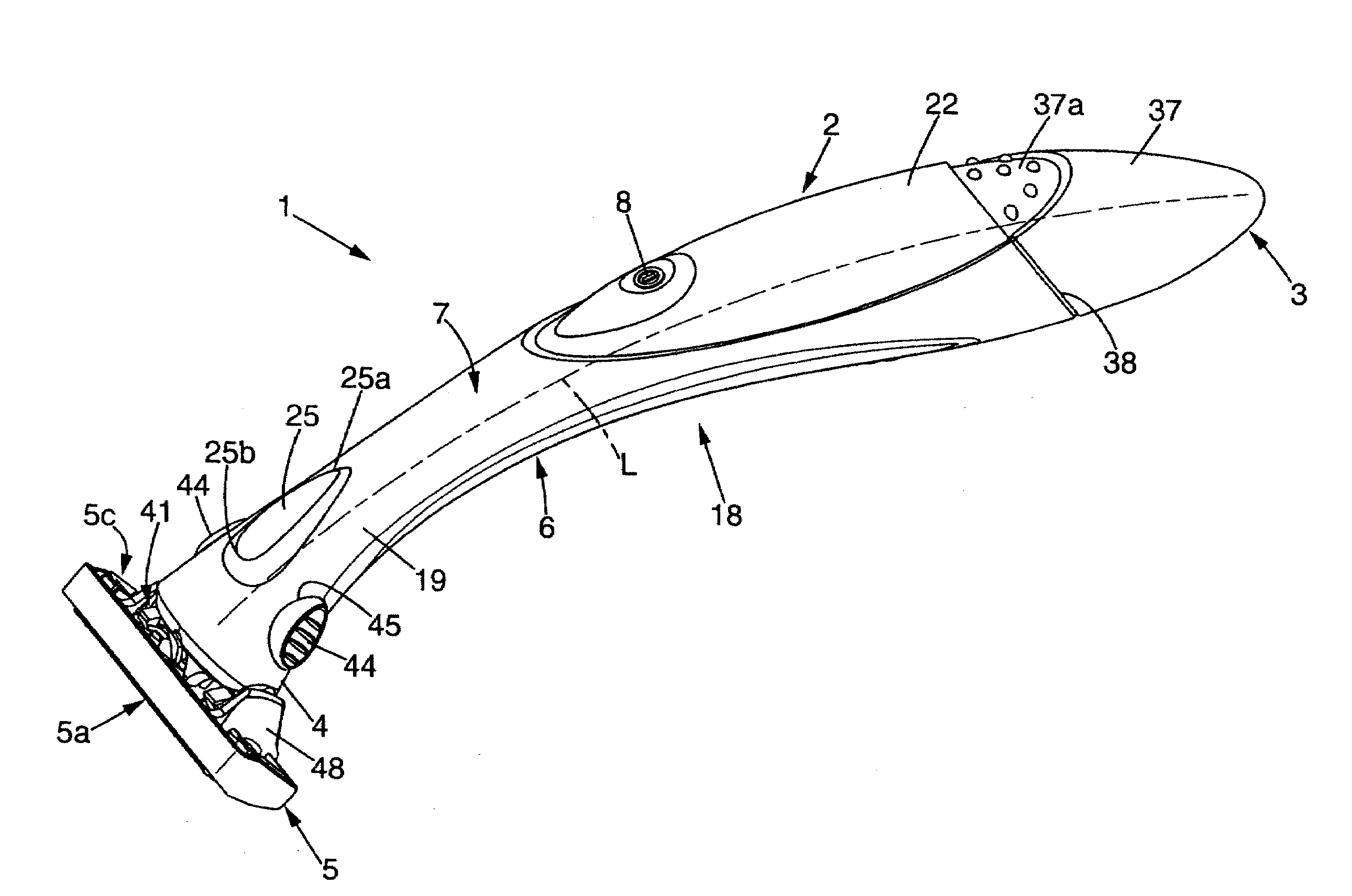
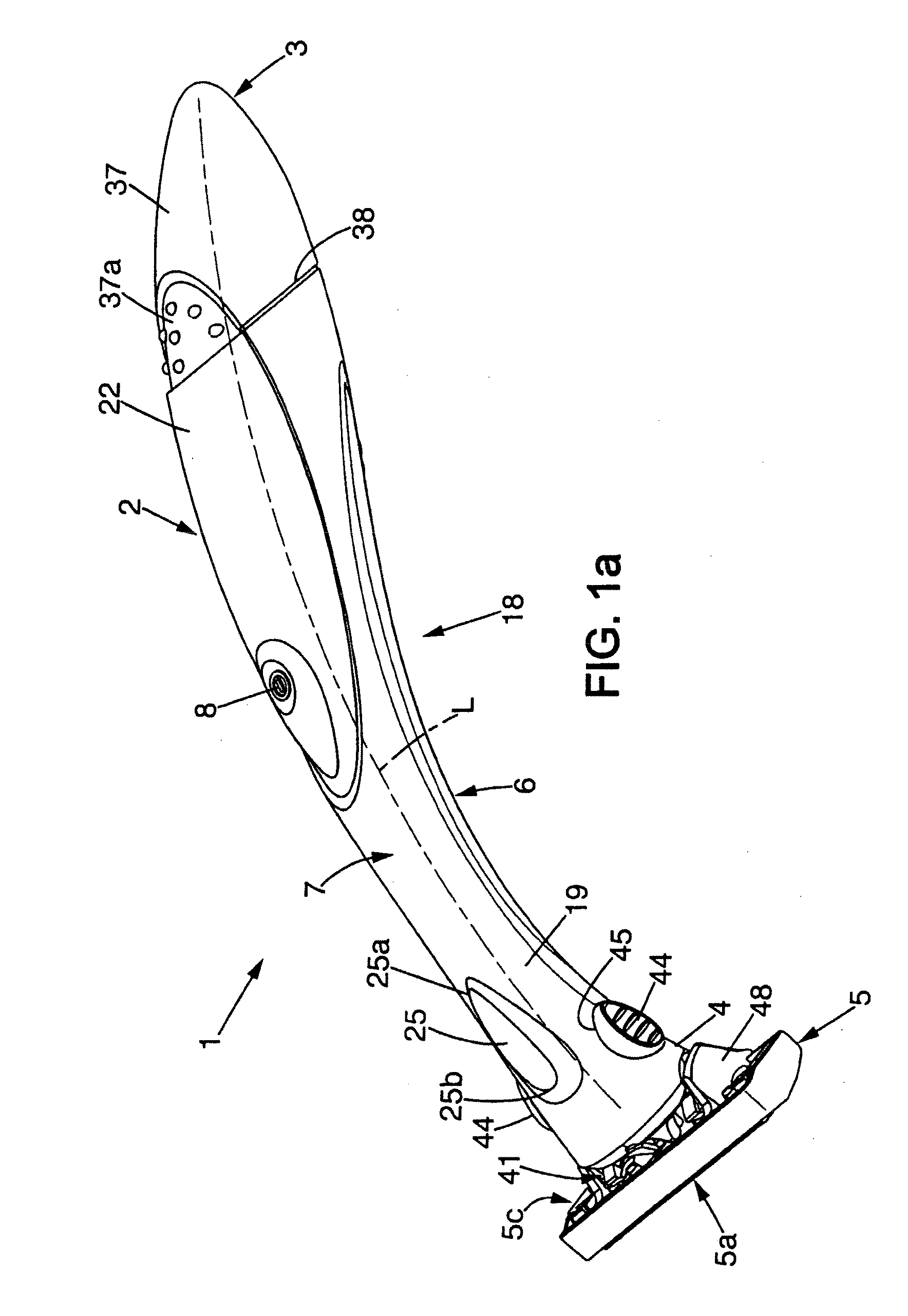
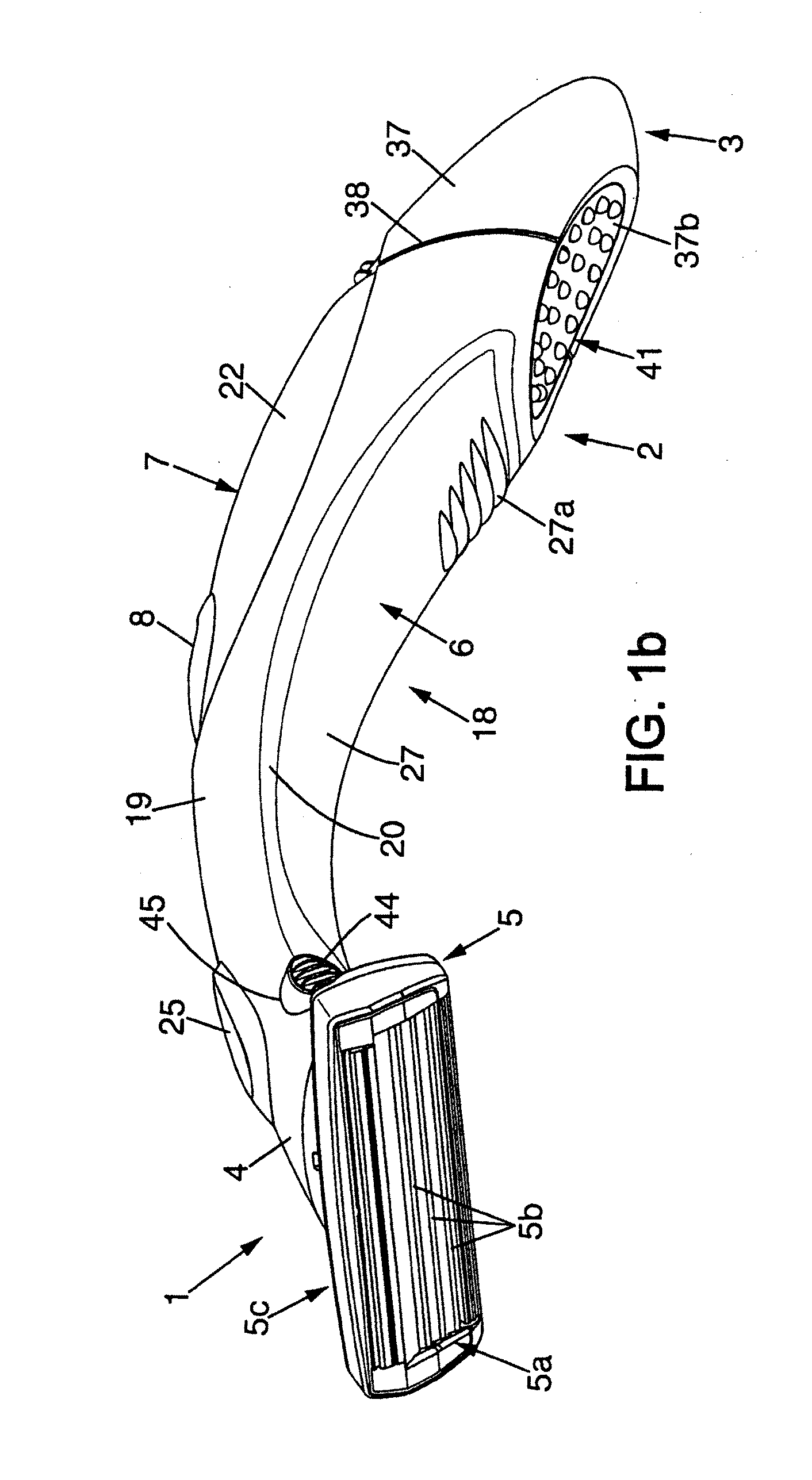
[0039]FIGS. 1a and 1b are respectively perspective views of a shaver according to the invention, seen from above and from below,

[0040]FIG. 2 is an exploded perspective of the shaver of FIGS. 1a and 1b, seen from above,

[0041]FIG. 3 is an exploded perspective view of the shaver of FIGS. 1a and 1b, seen from below,

[0042]FIG. 4 is a longitudinal cross section of the shaver of FIG. 1,

[0043]FIGS. 5-7 are respectively transverse cross sections along lines V-V, VI-VI and VII-VII of FIG. 4,

[0044]FIGS. 8a and 8b are two perspective views, seen in two different directions, of the lock / release mechanism connecting the razor handle to the shaving head in the shaver of FIGS. 1a and 1b,

[0045]FIG. 9 is a rear view of the shaving head in the shaver of FIGS. 1a and 1b,

[0046]FIGS. 10 and 11 are cross sections of the lock / release mechanism of FIGS. 8a and 8b, respectively in the head locking position and in the head release position, and

second embodiment

[0047]FIGS. 12 and 13 are similar views to FIGS. 6 and 7, in the invention.

[0048]In the figures, the same references denote identical or similar elements.

[0049]FIGS. 1a and 1b show a wet shaver 1, i.e. a shaver the blades of which are not driven by a motor relative to the shaving head.

[0050]The shaver 1 includes a hollow handle 2 extending in a longitudinal direction L between a proximal portion 3 and a distal portion 4 bearing a shaving head 5. The shaving head 5 includes a front face 5a equipped with one or several blades 5b and a rear face 5c which is connected to the handle 2.

[0051]The longitudinal direction L may be curved or include one or several straight portions. In the present case, the longitudinal direction L is curved, with a concavity which is constantly directed toward the underside 6 of the handle (i.e. the side of the handle which faces substantially the same direction as the front face 5a of the shaving head).

[0052]The shaver may further include, for instance on th...


PUM


Abstract

A vibrating wet shaver that includes a hollow handle, a shaving head borne by the handle, and an electric vibratory that includes a rigid casing that is fixed inside the handle for transmitting vibrations to the shaving head through the handle. The casing of the vibratory is tightly fitted in the handle, and at least an elastomeric layer is interposed between the casing and the handle.

Description

[0001]This application is a national stage application of PCT / FR2005 / 009621, filed on Sep. 6, 2005.[0002]The embodiments of the present invention relate to a vibrating shaver.FIELD OF THE INVENTIONBackground of the Invention[0003]More precisely, the embodiments of the present invention relates to a vibrating wet shaver (i.e., a shaver, the blades of which are not driven by a motor relative to the shaving head) comprising:[0004]a hollow handle,[0005]a shaving head borne by the handle, and[0006]an electric vibratory including a rigid casing which is fixed inside the handle, for transmitting vibrations to the shaving head through the handle.[0007]In vibrating shavers of this type, it is necessary to achieve an intimate contact between the rigid casing of the vibratory and the handle, in order to efficiently transmit vibrations from the electric vibratory to the handle and then from the handle to the shaving head.[0008]U.S. Pat. No. 5,299,354 discloses an example of such a known vibrati...

Claims


Application Information

Patent Timeline
IPC IPC(8): B26B19/28B26B21/00
CPCB26B21/38
Inventor BOZIKIS, IOANNIS
Owner BIC VIOLEX SA
Why Eureka
Try Eureka